Power Supply NGMO Unit Description
3-8 4.00 / 07-2004
Fig. 3-4 Circuit diagram: Mobile phone connected to the NGMO2
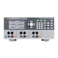
The NGMO2 provides:
• 2 channels15 V/2.5 (5) A with 7 A
pk
• fast output transient response
• sample buffer for fast current and voltage measurements
• internal and external triggers for current and voltage measurements
• separate DVM’s
• DC-load capability up to 2.8 A
• high voltage setting resolution
• precise low-current measurements
• very low ripple and noise
• settable output impedance for battery emulation
• OVP/OCP
• open sense detection
• auxiliary inputs/outputs (output inhibit, relay, complete)
• small dimensions (2 HU, half 19”)
• interfaces: IEEE488.2, RS232 and (USB)
• fast programming
• effective manual operation
 Loading...