Do you have a question about the Roland GI-10 and is the answer not in the manual?
Leading-edge pitch detection technology for fast guitar-to-MIDI conversion.
Allows voice or other forms of input to be output as MIDI data.
Easy-to-use interface with four buttons and clear panel display for quick operation.
Connect expression pedals and footswitches for volume control, vibrato, and hold effects.
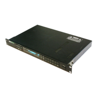
Optional adapter allows mounting on a 19-inch rack.
Use only the supplied AC adapter; turn off power before connecting devices; avoid cord damage.
Avoid temperature extremes, dust, humidity, vibration, and proximity to power amplifiers.
Wipe with a soft, dry cloth; use mild detergent for dirt; avoid solvents.
Protect from impact, liquid penetration, strong pressure on display; discontinue use if malfunction.
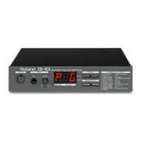
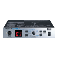
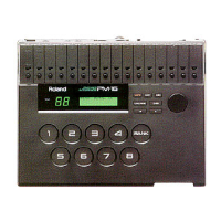
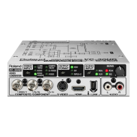
Identifies and describes the front panel controls: GK IN, MIC LEVEL, Display, Buttons, and Parameter Map.
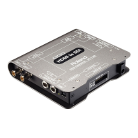
Details the rear panel connections: POWER, DC IN, MIDI OUT/IN, HOLD, and EXP PEDAL.
Explains GK IN, MIC IN, MIC LEVEL Knob, Display, Buttons, Power Switch, Power Supply Jack, MIDI Connectors, Hold Jack, and Expression Pedal Jack.
Instructions for connecting the GI-10 to MIDI units using MIDI cable, emphasizing powering off devices first.
Guide for attaching the optional RAD-50 rack mount adapter to the GI-10.
Refer to other sections for detailed connection methods and pedal switch information.
Explains that MIC IN has priority over GK IN; guitar data is not output if MIC IN is active.
Procedure to turn the GI-10 on and off using the rear panel power switch.
Instructions for using the internal tuner to tune a guitar connected to the GK IN connector.
Diagram and instructions for connecting the GI-10 and guitar to a MIDI sound generator.
Steps for triggering an external MIDI sound generator with a GK-2 series pickup.
Reiterates MIC IN priority over GK IN for simultaneous connections.
Configures the GI-10 to GK mode for outputting guitar performance data.
Adjusts the send mode to Poly or Mono to match the external MIDI sound generator.
Configures the MIDI transmit channel for sending data to the external sound generator.
Matches the GI-10's Bend Range setting to the external sound generator for accurate pitch changes.
Explains the function and settings of the Bend Range parameter for pitch bend data.
Configures the MIDI receive channel for input from the MIC IN jack.
Sets the Bend Range for the MIC IN signal to match the sound generator.
Assigns the desired sound to be played on the MIDI receive channel.
Configures GI-10 settings for optimal performance when using MIC IN.
Diagrams for connecting the GI-10 to sequencers and computers via MIDI or serial interfaces.
Illustrates connections to a MIDI sequencer and related equipment.
Shows connections to a computer using a MIDI interface board.
Illustrates direct connection to a computer via its serial I/O port.
Recommends Roland Super MPU for handling large MIDI data volumes from the GI-10.
Steps for setting GI-10 and sequencer for recording divided pickup guitar data.
Note on using Poly mode for sequencers not supporting multichannel recording.
Steps for setting GI-10 and sequencer for recording MIC IN data.
Note on MIC IN priority and outputting GK IN data.
Explains and guides the use of the Bend Data Thin feature to manage MIDI bend data volume.
Details how Bend Data Thin reduces MIDI bend data to prevent sequencer memory issues.
Explains and guides the use of the Attack Noise Filter to stabilize pitch before MIDI output.
Describes how the Attack Noise Filter waits for pitch stabilization for clearer MIDI notes.
Uses the Octave Shift function to output MIDI data one octave higher or lower than the guitar.
Connects and assigns functions (volume, vibrato) to an external expression pedal.
Connects a footswitch to the HOLD jack for sustain effects on external MIDI sound generators.
Optimized setting for finger picking, offering higher sensitivity than normal.
General-purpose picking setting.
Setting for hard pickers, offering lower sensitivity; may improve performance with close mounting.
External sound generator responds at a fixed volume, regardless of playing strength.
Adjusts the GI-10's middle A note frequency to match an external MIDI sound generator.
Uses S1/S2 switches on the GK-2 series unit to send Program Change messages to MIDI equipment.
Enables GK mode Program Changes and connects a MIDI foot controller for sound selection.
Diagram showing connection of MIDI keyboard/drum pad to the GI-10 MIDI IN.
Explains exclusive messages as manufacturer-specific MIDI data for parameter changes.
Shows connecting a computer via serial interface for remote parameter control.
Recommends Roland Super MPU for handling large MIDI data volumes from the GI-10.
Explains the checksum calculation for validating MIDI exclusive messages.
Explains the symbols used in the troubleshooting section for different connection types.
Diagnoses issues when the external sound generator does not produce sound.
Addresses problems with insufficient microphone input levels.
Checks if the play mode is set to GK for proper performance data output.
Checks if the play mode is set to MIDI IN for proper MIDI data reception.
Identifies MIC IN jack priority as a cause for GK IN data not being output.
Ensures transmit and receive MIDI channels are set to the same number.
Lists the Play Mode parameter, its values (GK, MIDI IN), display, and page reference.
Lists the MIDI CH parameter, its values (1-16), display, and page reference.
Lists the Bend Range parameter, its values (0, 2, 12, 24), display, and page reference.
Lists the Poly/Mono parameter, its values (POLY, MONO), display, and page reference.
Lists the Octave Shift parameter, its values (down, normal, up), display, and page reference.
Lists the Bend D.THIN parameter, its values (off, normal, on), display, and page reference.
Lists the Attack N.FLT parameter, its values (off, on), display, and page reference.
Lists the Pedal Assign parameter, its values (Expression, Modulation), display, and page reference.
Lists the Touch SENS parameter, its values (finger, normal, hard, no.dynamics), display, and page reference.
Lists the Pickup SENS parameter, its values (1-4-8), display, and page reference.
Lists the Master Tune parameter, its values (440.0 Hz, 442.0 Hz), display, and page reference.
Lists the Tuner parameter, its value (9.1), display, and page reference.
Step-by-step guide to reset all GI-10 settings to their factory defaults.
Details transmitted and recognized MIDI functions, including Basic Channel, Mode, Note Number, Velocity, etc.
Lists MIDI Control Change messages and their corresponding values and functions.
Details Program Change messages, their range, and remarks.
Indicates support for System Exclusive MIDI messages.
Details System Common MIDI messages like Song Position and Tune.
Details System Real Time MIDI messages like Clock and Commands.
Details Auxiliary MIDI messages like All Notes OFF and Active Sense.
Provides notes on memorization after power off and mode definitions.
Describes the GI-10's display type: an 8-segment, 3-character LED.
Lists all available connectors and jacks on the GI-10 unit.
Details the power requirements: DC 9 V via AC adaptor.
States the power consumption of the GI-10 is 260 mA.
Provides the physical dimensions of the GI-10 in millimeters and inches.
States the weight of the GI-10 as 1.3 kg (2 lbs 14 oz) excluding the AC adaptor.
Lists the accessories included with the GI-10: User's Manual, AC Adaptor, cables.
Lists optional accessories available for purchase, such as GK-2A driver and expression pedal.
Tips for clear vocal input: close mouth, enunciate, strong attack, avoid consecutive lyrics.
Tips for converting non-vocal sounds; microphone type and setup affect conversion accuracy.
Emphasizes playing only single notes for accurate MIDI conversion via MIC IN, not chords.
Notes that guitar input via MIC IN might have slower response than GK IN for lower strings.
Specifies the recognizable input note range (E2-D6) for the MIC IN jack for reliable conversion.
States the maximum input level (230 mV RMS) for the MIC IN jack; exceeding it may cause unreliable conversion.
| Brand | Roland |
|---|---|
| Model | GI-10 |
| Category | Media Converter |
| Language | English |