33
Quick Guide Overview Outputting Sound Eects Saving Pedal Settings System MIDI/USB Appendix
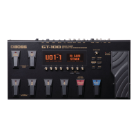
Pedal Settings (Control/Expression)
Using Pedals to Control the
Parameters
Here’s how to assign the parameters that will be controlled by the
ACCEL/CTL, EXP, SUB EXP, SUB CTL1, and SUB CTL2 pedals.
For details on each pedal, refer to “Front Panel” (p. 20) and ”Rear Panel
(Connections)” (p. 22).
Assigning the ACCEL/CTL, EXP SW, SUB
CTL1, and SUB CTL2 Functions
1. Press the [CTL/EXP] button.
2. Turn knob [4] to select the pedal whose assignment you
want to specify.
3. Use knob [5]–[8] to set the parameter that you want to
control.
Parameter Value Explanation
Page 1
[5] FUNC
You can assign a variety of functions, such as
turning each eect on/o or switching the preamp
channel. For details on all parameters, download the
“GT-100 Parameter Guide” (PDF le) located under
“GT-100” in the list of “Owner’s Manuals” on the
Roland website (http://www.roland.com/support/
en/).
[6] MIN
OFF, ON
(or STOP, START)
This sets the value for times
when the switch is O.
[7] MAX
OFF, ON
(or STOP, START)
This sets the value for times
when the switch is On.
[8]
SOURCE
MODE
This sets the behavior of the value each time the
switch is operation.
MOMENT
The normal state is O
(minimum value), with the
switch On (maximum value)
only while the footswitch is
depressed.
TOGGLE
The setting is toggled On
(maximum value) or O
(minimum value) with each
press of the footswitch.
* To be able to apply an Accel eect (p. 19) using the ACCEL/CTL
control pedal, you need to set ACCEL/CTL FUNC to ACCEL, and
set SOURCE MODE to MOMENT.
4. Press the [EXIT] button to return to the Play screen.
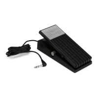
Connect your foot switch to the SUB CTL 1, 2/SUB EXP jack as shown in the illustration, and set its POLARITY switch.
POLARITY switch
When Connecting an FS-5U
When Connecting Two FS-5Us When Connecting an FS-6
Cable:
Stereo 1/4” phone type
1/4” phone type x 2
MODE/POLARITY switch
Cable:
1/4” phone type
fg
1/4” phone type
Cable:
Stereo 1/4” phone type fg
Stereo 1/4” phone type
or or

 Loading...