9—Working with Input Signals
Roland VS-2480 Owner’s Manual www.rolandus.com 131
Digital Input Signals
Digital Connections
The VS-2480 can accept digital audio from an external digital device through the
VS-2480’s S/P DIF stereo coaxial and optical inputs or via its two R-BUS connectors. To
learn about connecting devices to these jacks, see Page 49.
Selecting the Desired Digital Inputs
The VS-2480 can receive up to 16 digital audio signals at a time (in addition to 16 analog
input signals). The eight digital audio inputs provided by the R-BUS 1 jack are always
available. You can select the remaining eight digital inputs from among the 12 offered
by the R-BUS 2, coaxial and optical jacks. The R-BUS 2 jack has eight digital audio
inputs, and the coaxial and optical jacks provide a stereo pair each.
Activating R-BUS 2, Coaxial or Optical Digital Inputs
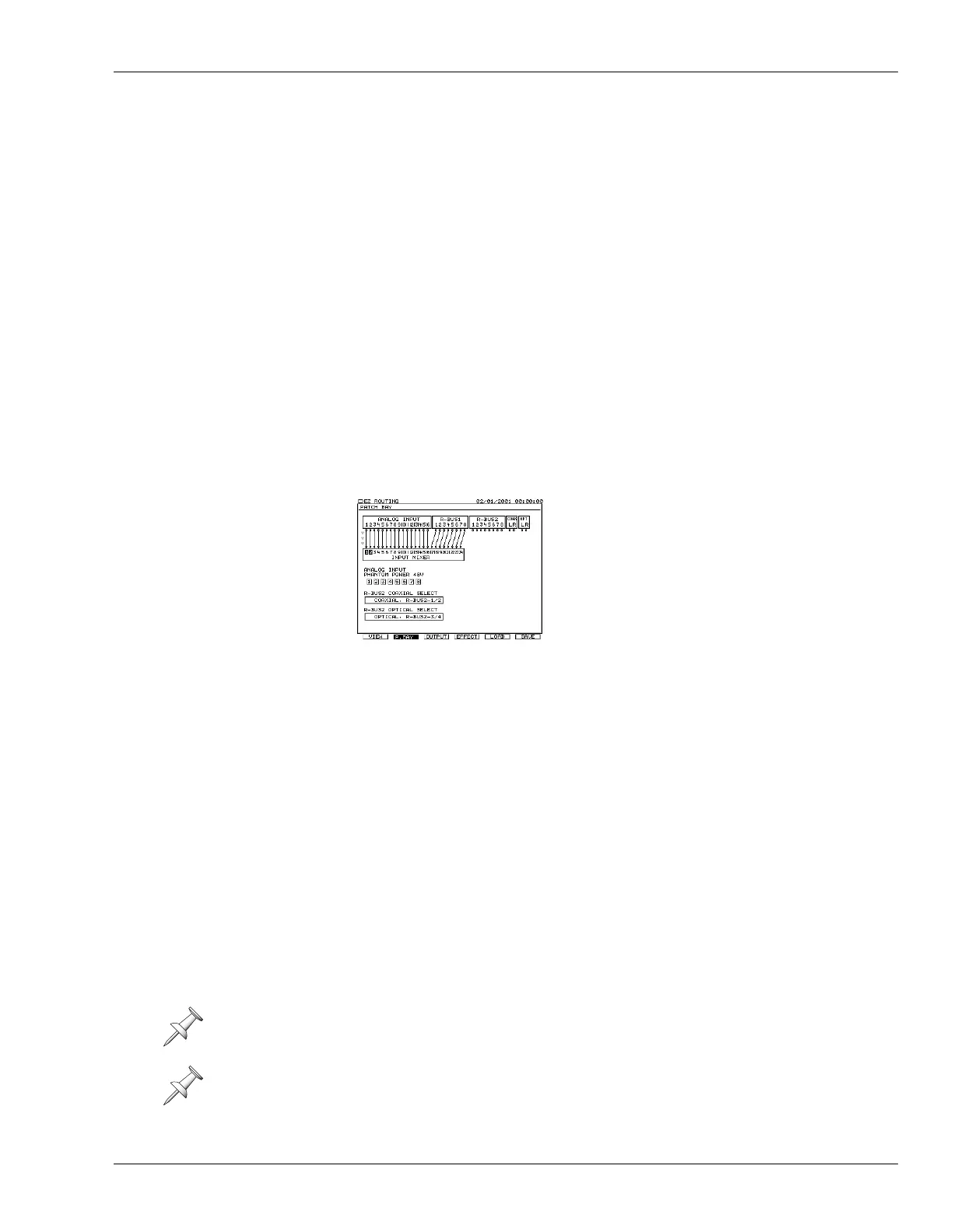
1. Hold down SHIFT and press EZ•ROUTING—the PATCH BAY screen appears.
2. Press
until R-BUS2 COAXIAL SELECT is highlighted, as shown here.
The settings of the R-BUS2 COAXIAL SELECT and R-BUS2 OPTICAL SELECT
parameters select the R-BUS 2, coaxial and/or optical inputs you want to use.
3. Turn the TIME/VALUE dial to select one of the following values:
• R-BUS21/2,R-BUS25/6—to activate R-BUS 2 Channels 1, 2, 5 and 6, and de-
activate the coaxial digital input.
• COAXIAL, R-BUS21/2—To activate the coaxial digital input and R-BUS 2
Channels 1 and 2.
• COAXIAL, R-BUS25/6—To activate the coaxial digital input and R-BUS 2
Channels 5 and 6.
4. Press
to highlight R-BUS2 OPTICAL SELECT.
5. Turn the TIME/VALUE dial to select:
• R-BUS2 3/4,R-BUS2 7/8—to activate R-BUS 2 Channels 3, 4, 7 and 8, and de-
activate the optical digital input.
• COAXIAL, R-BUS2 3/4—To activate the optical digital input and R-BUS 2
Channels 3 and 4.
• COAXIAL, R-BUS2 7/8—To activate the optical digital input and R-BUS 2
Channels 7 and 8.
6. Route your active inputs to the desired input channels as described on Page 135.
To turn on all eight R-BUS 2 inputs, select R-BUS2 1/2,R-BUS2 5/6 for R-BUS2
COAXIAL SELECT, and R-BUS2 3/4,R-BUS2 7/8 for R-BUS2 OPTICAL SELECT.
The R-BUS2 COAXIAL SELECT and R-BUS2 OPTICAL SELECT parameters can also
be found on the UTILITY menu’s PROJECT PARAMETER screen.
This illustration shows the
PATCH BAY screen as it appears
after a new project is created and
with its first page displayed. You
can activate phantom power from
either PATCH BAY page.
VS2480OMUS.book 131 ページ 2006年2月7日 火曜日 午後4時16分

 Loading...