Part No 4801-5156 Rev 1-2017 RollSeal SC-325 & SC-650 Controllers Page 21
Three Position
Operator Switch
Manual
Activated
Timed
Activated
Open
Activated
Close
Activated
Stop Activated Notes
During the specific
operation below…..
TIMED Opening
N/A N/A N/A N/A Stops Door after 1-2
Seconds
TIMED Closing
N/A Reopens Door
& Starts Delay
N/A N/A Stops Door (Immediately)
During TIMED
Countdown
Closes
Immediately
Restarts Time
Delay
Exits
Time
Delay
Closes
Door
Should Terminate Timed
Cycle
MANUAL
Opening
N/A N/A N/A N/A
Stops Door after 1-2
Seconds
When Stop is
pressed & door
stops, pressing the
Manual button again
will cause the door
to reverse direction
at that point.
MANUAL Closing
N/A Opens then
starts Time
Delay
N/A N/A
Stops Door
(Immediately)
While Completely
Open (after
MANUAL)
Closes N/A N/A Closes
Door
N/A
While OPENing
N/A N/A N/A N/A Stops Door after 1-2
Seconds
While CLOSing
N/A Reopens door
& starts Time
Delay
N/A N/A Stops Door (Immediately)
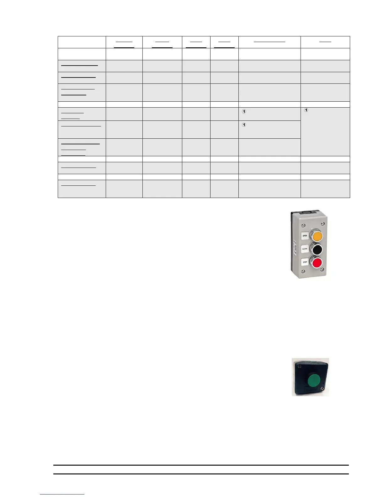
8.1 Directional Switch Input
The directional switch input is primarily for use with a three position direction
switch similar to the one illustrated below. Operation is simple. Momentarily push
“OPEN” to open the door, momentarily push “CLOSE” to close the door and
momentarily push “STOP” to stop the door. However, the SC-325 and SC-650
controller can be programmed to perform special events with these directional
switches.
For example, if the ‘STOP” button is pressed and held, the door will remain in the
stopped position. None of the other control switches will operate as long as the
“STOP” connection to the controller is completed. Similarly, if the “OPEN”
button is pressed and held, the door will remain in the open position. And, if the
“CLOSE” button is pressed and held, the door will remain in the closed position.
These features would be useful if an operator wanted to “lock” the door in a
particular position with the use of external switches connected in parallel with the directional switch.
For safety reasons, these directional buttons have a priority built into the controller in case one or more of the
buttons are closed at the same time. The “STOP” switch has first priority, the “OPEN” has second priority
and the “CLOSE” has third priority.
Section 12.6 and 12.7 shows the connections for the directional, manual and timed switch inputs to the
controller.
8.2 Manual (Single) Switch Input
This switch provides a conventional means of connecting a single button that
responds to each momentary press sequentially. For example, if the last
movement of the door was in the open direction and the manual input is made,
the door will attempt to close. Conversely, if the last movement of the door was
in the close direction and the manual input is made, the door will attempt to
open. If this single position manual switch is used with the three position
directional switch as discussed above, the manual switch has fourth priority.
Section 12.6 and 12.7 shows the connections for the directional, manual and timed switch inputs to the
controller.
NOTE: This input will be reconfigured for use with the Interlock circuit if the P4 setting is
programmed to anything other than zero. See Setting P4 under Section 6.1 for more
information.
Singe Position
O
erator Switch
 Loading...