© 2017 Ropam Elektronik
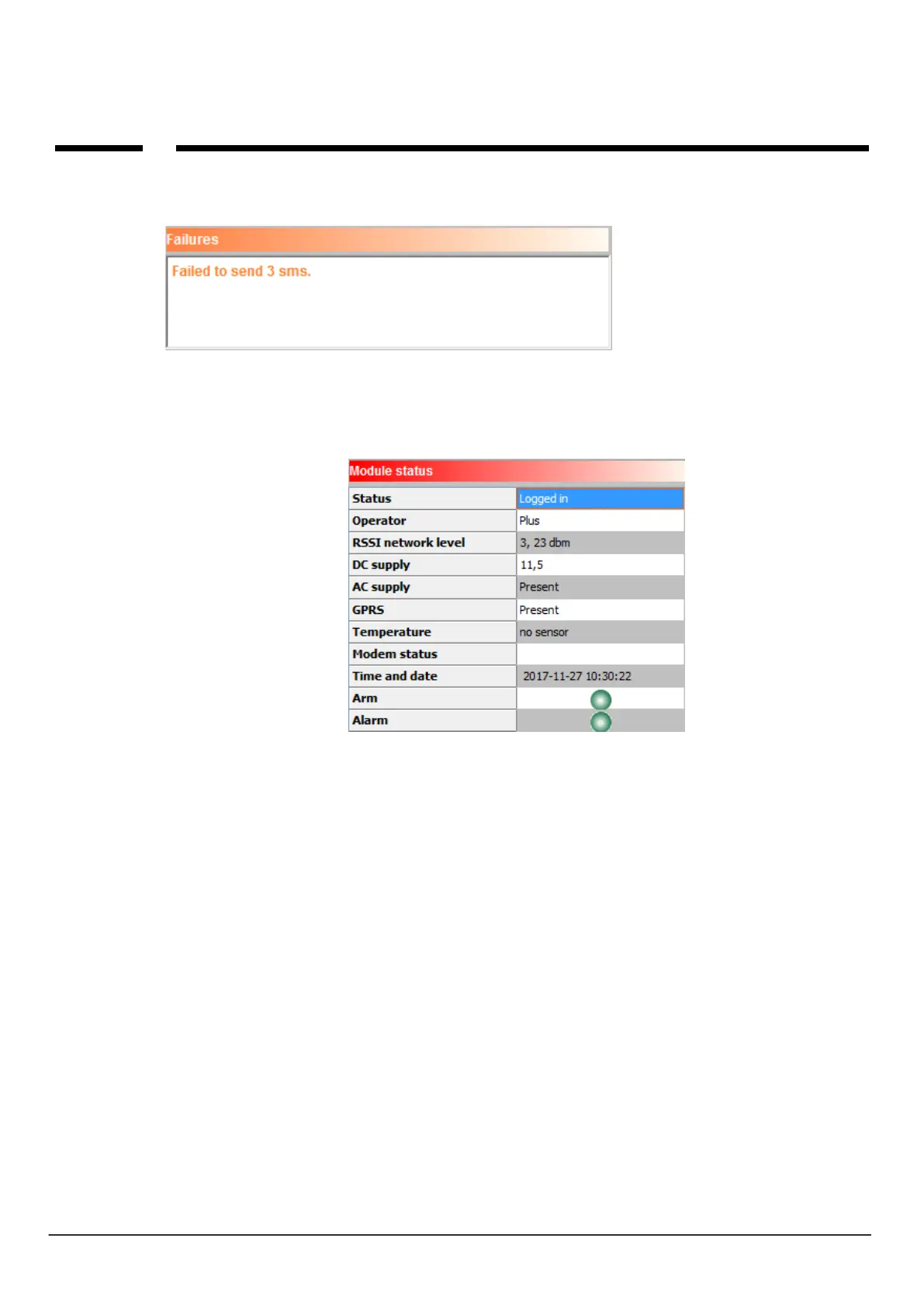
FAILURES:
View current faults in the module (eg low voltage supply, GSM signal interruption, battery voltage low,
SIM card problem).
MODULE STATUS:
Current module status:
Status: - logged in, not logged in,
Operator: - name of the SIM card operator inserted into the SIM card connector in the module,
RSSI network level: - GSM signal level, "dashes" 1-4 where 1 = weak, 4 = very good, dBm - signal
level,
DC voltage: DC supply voltage of the module,
AC voltage: AC voltage indicator connected to: FAC input for BasicGSM 2 (works when AC detection
enabled) connected to the module's power terminals for BasicGSM - PS 2,
GPRS: is, none. Indicator of presence of GPRS module,
Temperature: The temperature indicator from the TSR-xx sensor connected to the T1 connector.
Accuracy of readings at 0,5st [C], measurement every 30 [s].
Modem status: Modem activity indicator: sending SMS, email, ringing, incoming call (icons),
Time and date: current date and time in module,
Arming: Module arming indicator (red semaphore - on, green semaphore - off),
Alarm: alarm presence indicator in module (red semaphore - was / is alarm, green semaphore - no
alarms),