23
8.2.2 Bench Check. Sensor simulation may be used
to check the operation of the Model 2081. If the Model
2081 is using the integral preamplifier, connect the
simulator(s) according to Figur
e 8-1. If the model 2081
has no preamplifier, connect the simulator(s) as shown
in Figure 8-2. Refer to Table 8-2 for the appropriate
RTD resistance.
CAUTION
Do not use over 55 volts to check the loop, or
damage to the transmitter electronics may
result.
1. After completing power and simulator(s) wiring,
apply 24Vdc power to the Model 2081.
2. Simulate 25°C to the transmitter by placing 110
resistance between TB6 and TB8. The Model 2081
should display ~25°C (refer to Section 3.2.1).
Adjust the temperature display if necessary (Refer
to Section 5.2).
3. Simulate 4 pH by applying +177 millivolts dc
(
W
/integral preamplifier) or +1.52 VOLTS DC (
W
/O
preamplifier).
NOTE
Using mV inputs for units without preamps will
result in a “SnSr FAIL” fault code.
4. Depress and hold both push buttons to scroll
through the menu items to “buF1” then release
both buttons. The display will show the pH value
currently in “buF1” memory.
5. Depress and hold push button #1 (scroll) then #2
(shift) as needed to display 4.00.
6. ENTER the value into memory by simultaneously
depressing both push buttons briefly.
7. Simulate 10 pH by applying -177 millivolts dc
(
W
/preamplifier) or 1.173 VOLTS DC (
W
/O pream-
plifier).
8. Follow steps 4-6 for “buF2”, entering 10.0pH.
9. The Model 2081 should display ~ 10.00.
10. If the transmitter performs properly, then the sen-
sor should be checked.
If the integral preamplifier is suspect, bypass it and
follow the instructions for calibration without the pre-
amplifier.
8.2.3 Sensor Troubleshooting. In addition to the fault
mnemonics that relate to a possible sensor problem
(Table 8-1 and Table 8-5), the transmitter can display
the input in millivolts generated from the sensor. See
Table 8-3 for how the millivolt input relates to pH. If the
transmitter values are not within about 20% of those in
Table 8-3, the transmitter has been incorrectly stan-
dardized for pH, the reference may be significantly
poisoned, or some other significant problem exists. To
read the millivolt input, go to “inPt” in the display sub-
menu.
*99% pH electrode efficiency
8.2.4 PCB Stack Replacement. If it becomes neces-
sary to replace the PCB stack (both CPU and Sensor
boards) there is no need to field calibrate electronics
upon replacement, since the millivolt input and output
digital trim is performed at the factory. Simply remove
the old assembly, reconnect the new stack, and per-
form the sensor calibration.
8.2.5 LCD Display Replacement. If the display board
needs to be replaced you will need both the generic
display assembly P/N 23419-00 and the pH overlay
P/N 9240008-00.
CAUTION
Remove power from transmitter before
removing the electronics cover.
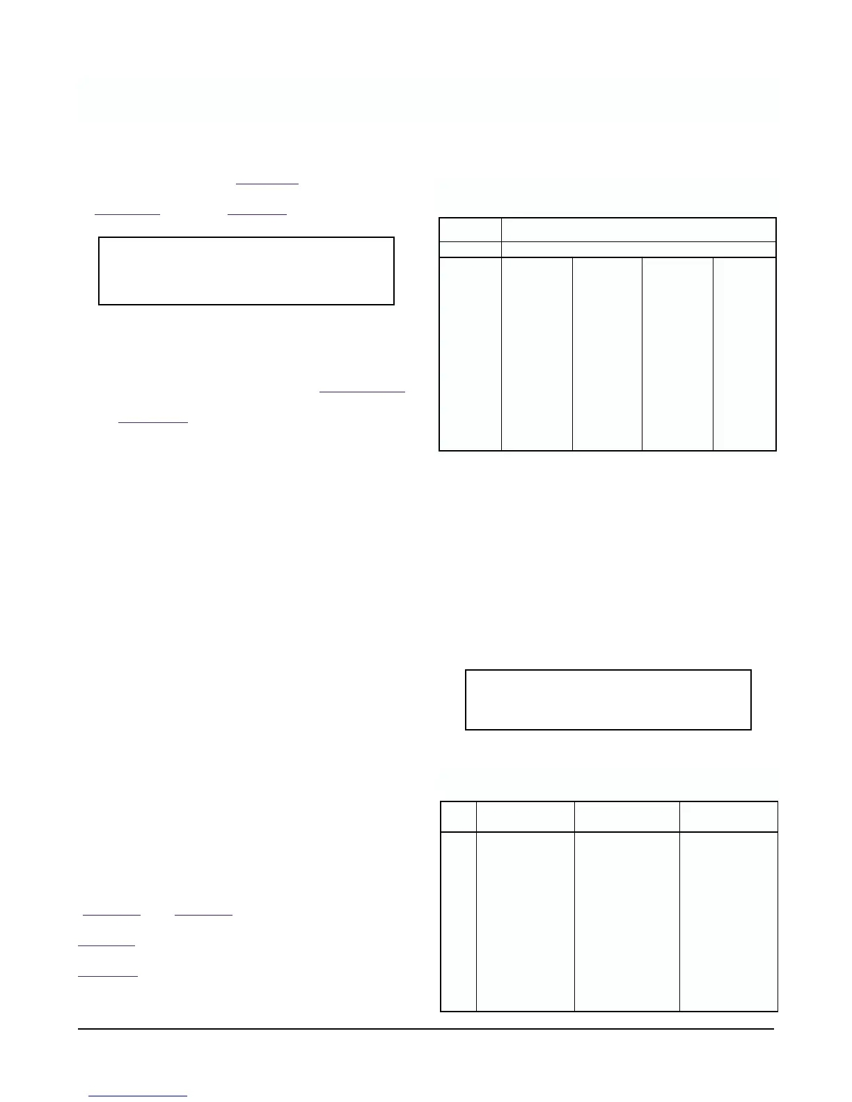
pH Input to Transmitter in MILLIVOLTS
15°C
(59°F)
25°C
(77°F)
50°C
(122°F)
80°C
(176°F)
0 396 410 444 486
1 340 351 381 416
2 283 293 317 347
3 226 234 254 277
4 170 176 190 208
5 113.2 117.1 127.0 138.7
6 56.6 58.6 63.5 69.4
70000
8 –56.6 –58.6 –63.5 –69.4
9 –113.2 –117.1 –127.0 –138.7
10 –170 –176 –190 –208
11 –226 –234 –254 –277
12 –283 –293 –317 –347
13 –340 –351 –381 –416
14 –396 –410 –444 –486
TABLE 8-3. Sensor Input* to Transmitter Verses
pH at Four Temperatures
15°C
(RTD = 105.85 )
25°C
(RTD = 109.74 )
80°C
(RTD = 130.89 )
pH Vdc input Vdc input Vdc input
0 1.75 1.76 1.84
1 1.69 1.71 1.77
2 1.63 1.65 1.70
3 1.58 1.59 1.63
4 1.52 1.53 1.56
5 1.47 1.47 1.49
6 1.41 1.41 1.42
7 1.35 1.35 1.35
8 1.29 1.29 1.28
9 1.24 1.23 1.21
10 1.18 1.17 1.14
11 1.12 1.11 1.07
13 1.01 1.00 0.93
14 0.95 0.94 0.86
TABLE 8-4
VOLTAGE Input to Transmitter (no integral preamplifier)
MODEL 2081 pH SECTION 8.0
DIAGNOSTICS AND TROUBLESHOOTING