Reference Manual
00809-0100-4809, Rev DA
Appendix A: Specifications and Reference Data
September 2015
112
Specifications and Reference Data
4–20 mA/HART
Zero and span adjustment
Zero and span values can be set anywhere within the
range.
Span must be greater than or equal to the minimum span.
Output
Two-wire 4–20 mA is user-selectable for linear or square
root output. Digital process variable superimposed on
4–20 mA signal, available to any host that conforms to the
HART protocol.
Power supply
External power supply required
3051SF_D: 10.5 to 42.4 Vdc with no load
3051SF_D with Advanced HART Diagnostics Suite: 12
to 42.4 Vdc with no load
3051SF_1-7: 12 to 42.4 Vdc with no load
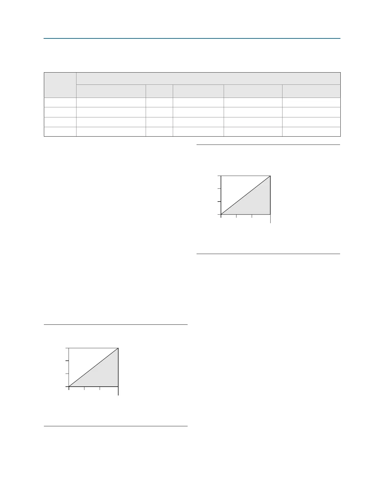
Load limitations
Maximum loop resistance is determined by the voltage
level of the external power supply, as described by:
Figure 1. 3051SF_D
Figure 2. 3051SF_1-7 and 3051SF_D with HART
Diagnostics (Option Code DA2)
Advanced HART diagnostics suite (option code DA2)
The 3051SF provides Abnormal Situation Prevention
indication for a breakthrough in diagnostic capability. The
3051SF ASP Diagnostics Suite for HART includes Statistical
Process Monitoring (SPM), variable logging with time
stamp and advanced process alerts. The enhanced EDDL
graphic display provides an intuitive and user-friendly
interface to better visualize these diagnostics.
The integral SPM technology calculates the mean and
standard deviation of the process variable 22 times per
second and makes them available to the user. The 3051SF
uses these values and highly flexible configuration options
for customization to detect many user-defined or
application specific abnormal situations (e.g. detecting
plugged impulse lines and fluid composition change).
Variable logging with time stamp and advanced process
alerts capture valuable process and sensor data to enable
quick troubleshooting of application and installation
issues
Fluid Compatibility with Pressure and Temperature Compensation
• Available
— Not available
Ordering
code
Fluid types
Measurement type
Liquids Saturated steam Superheated steam Gas and natural gas
1 DP/P/T (Full Compensation) • • • •
2 DP/P • • • •
3 DP/T • • — —
4 DP only • • — —
Maximum Loop Resistance = 43.5 ⫻ (Power Supply Voltage – 10.5)
The Field Communicator requires a minimum loop resistance of
250 for communication.
1387
1000
500
0
10.5 20 30
42.4
Voltage (Vdc)
Load (Ohms)
Operating
Region
Maximum Loop Resistance = 43.5 ⫻ (Power Supply Voltage – 12.0)
The Field Communicator requires a minimum loop resistance of
250 for communication.
1322
1000
500
0
12.0 20 30
42.4
Voltage (Vdc)
Load (Ohms)
Operating
Region