Reference Manual
00809-0100-4809, Rev DA
Appendix A: Specifications and Reference Data
September 2015
135
Specifications and Reference Data
Long term stability
Dynamic performance
Vibration effect
Less than ±0.1% of URL when tested per the requirements of
IEC60770-1 field or pipeline with high vibration level (10-60
Hz 0.21 mm displacement peak amplitude/60-2000 Hz 3g).
A.6.3 Physical specifications
Electrical connections
1
/2–14 NPT, PG 13.5, G
1
/2, and M20 ⫻ 1.5 conduit. HART
interface connections fixed to terminal block.
Process-wetted parts
Drain/vent valves
316 SST, Alloy C-276, or Alloy 400 material (Alloy 400 not
available with 3051L)
Process flanges and adapters
Plated carbon steel, SST cast CF-8M (cast version of 316
SST, material per ASTM-A743), C-Type cast alloy
CW12MW, or cast alloy M30C
Wetted O-rings
Glass-filled PTFE or Graphite-filled PTFE
Process Isolating Diaphragms
Alloy C-276, Alloy 400, Tantalum, Gold-plated Alloy 400,
Gold-plate SST
Non-wetted parts
Electronics housing
Low-copper aluminum or CF-8M (Cast version of 316 SST).
Enclosure Type 4X, IP 65, IP 66, IP 68
Coplanar sensor module housing
CF-3M (Cast version of 316L SST, material per
ASTM-A743)
Bolts
ASTM A449, Type 1 (zinc-cobalt plated carbon steel)
ASTM F593G, Condition CW1 (Austenitic 316 SST)
ASTM A193, Grade B7M (zinc plated alloy steel)
Alloy K-500
Sensor module fill fluid
Silicone oil (D.C. 200)
Paint
Polyurethane
Cover o-rings
Buna-N
Models Long term stability
3051CF
Ranges 2-3 ±0.125% of URL for 5 years
±50 °F (28 °C) temperature changes, and up to 1000 psi (6,9 MPa) line pressure
3051CF Low/Draft Range
Range 1 ±0.2% of URL for 1 year
4 - 20 mA
(HART protocol)
(1)
Fieldbus protocol
(3)
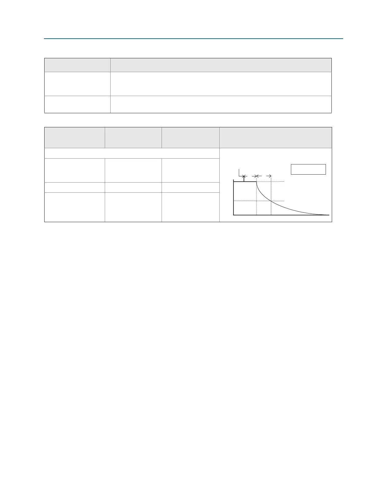
Typical HART transmitter response
time
Total Response Time (T
d
+ T
c
)
(2)
:
3051CF,
Ranges 2-5:
Range 1:
100 ms
255 ms
152 ms
307 ms
Dead Time (T
d
) 45 ms (nominal) 97 ms
Update Rate 22 times per second 22 times per second
1. Dead time and update rate apply to all models and ranges; analog output only.
2. Nominal total response time at 75 °F (24 °C) reference conditions.
3. Transmitter Fieldbus output only, segment macro-cycle not included.
Pressure released
T
d
T
c
Transmitter Output vs. Time
100%
36.8%
0%
Time
63.2% of total
step change
= Dead time
= Time constant
T
d
T
c
Response time =
T
d
+
T
c