Reference Manual
00809-0100-4809, Rev DA
Appendix A: Specifications and Reference Data
September 2015
153
Specifications and Reference Data
Failure mode alarm
If self-diagnostics detect a sensor or microprocessor failure,
the analog signal is driven either high or low to alert the user.
High or low failure mode is user-selectable with a jumper on
the transmitter. The values to which the transmitter drives its
output in failure mode depend on whether it is
factory-configured to standard or NAMUR-compliant
operation. The values for each are as follows:
Output code F
If self-diagnostics detect a gross transmitter failure, that
information gets passed as a status along with the process
variable.
Long term stability
Dynamic performance
Vibration effect for 2051CFA, 2051CFC, and 2051CFP
Less than ±0.1% of URL when tested per the requirements of
IEC60770-1 field or pipeline with high vibration level
(10-60 Hz, 0.21 mm displacement peak amplitude/
60-2000 Hz 3g).
Vibration effect for 2051CFC_A
Less than ±0.1% of URL when tested per the requirements
of IEC60770-1 field or pipeline with high vibration level
(10-60 Hz, 0.15 mm displacement peak amplitude/
60-2000 Hz 2g).
(1)
Standard operation
Output
code
Linear output Fail high Fail low
A 3.9 I 20.8 I 21.75 mA I 3.75 mA
M 0.97 V 5.2 V 5.4 V V 0.95 V
NAMUR-compliant operation
Output
code
Linear output Fail high Fail low
A 3.8 I 20.5 I 22.5 mA I 3.6 mA
Models Standard
Performance
option, P8
2051CF
Range 1 (CF)
±0.2% of URL for 1 year,
Reference Stability
±0.125% of URL
for 5 years,
Operating
Stability
Ranges 2-5
±0.1% of URL for 2 years,
Operating Stability
4-20 mA HART
(1)
1-5 Vdc HART low power
1. Dead time and update rate apply to all models and ranges; analog output only.
FOUNDATION
Fieldbus
(2)
2. Transmitter Fieldbus output only, segment macro-cycle not included.
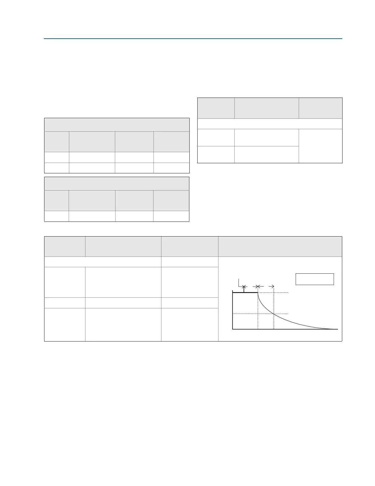
Typical HART transmitter response time
Total Response Time (T
d
+ T
c
)
(3)
:
3. Nominal total response time at 75 °F (24 °C) reference conditions.
2051CF,
Range 3-5
Range 1
Range 2
115 milliseconds
270 milliseconds
130 milliseconds
152 milliseconds
307 milliseconds
152 milliseconds
Dead Time (T
d
) 60 milliseconds (nominal) 97 milliseconds
Update Rate 22 times per second 22 times per second
Pressure released
T
d
T
c
Transmitter Output vs. Time
100%
36.8%
0%
Time
63.2% of total
step change
= Dead time
= Time constant
T
d
T
c
Response time =
T
d
+
T
c
1. Stainless steel temperature housing is not recommended with primary element technology A in applications with mechanical vibration.