10
Reference Manual
00809-0100-4378, Rev CE
Section 2: Installation
February 2014
Installation
It is recommended that the 751 indicator be wired in a parallel configuration when the 4-20 mA
transmitter includes a test terminal. Utilization of the test terminal is required in a parallel
configuration. Connecting the 751 indicator across the positive and negative terminals of the
4-20 mA transmitter could impact the loop.
A parallel configuration will allow the removal of the 751 indicator without affecting the
integrity of the 4-20 mA loop. Additionally, spare 751 indicators can be added without
disrupting the loop.
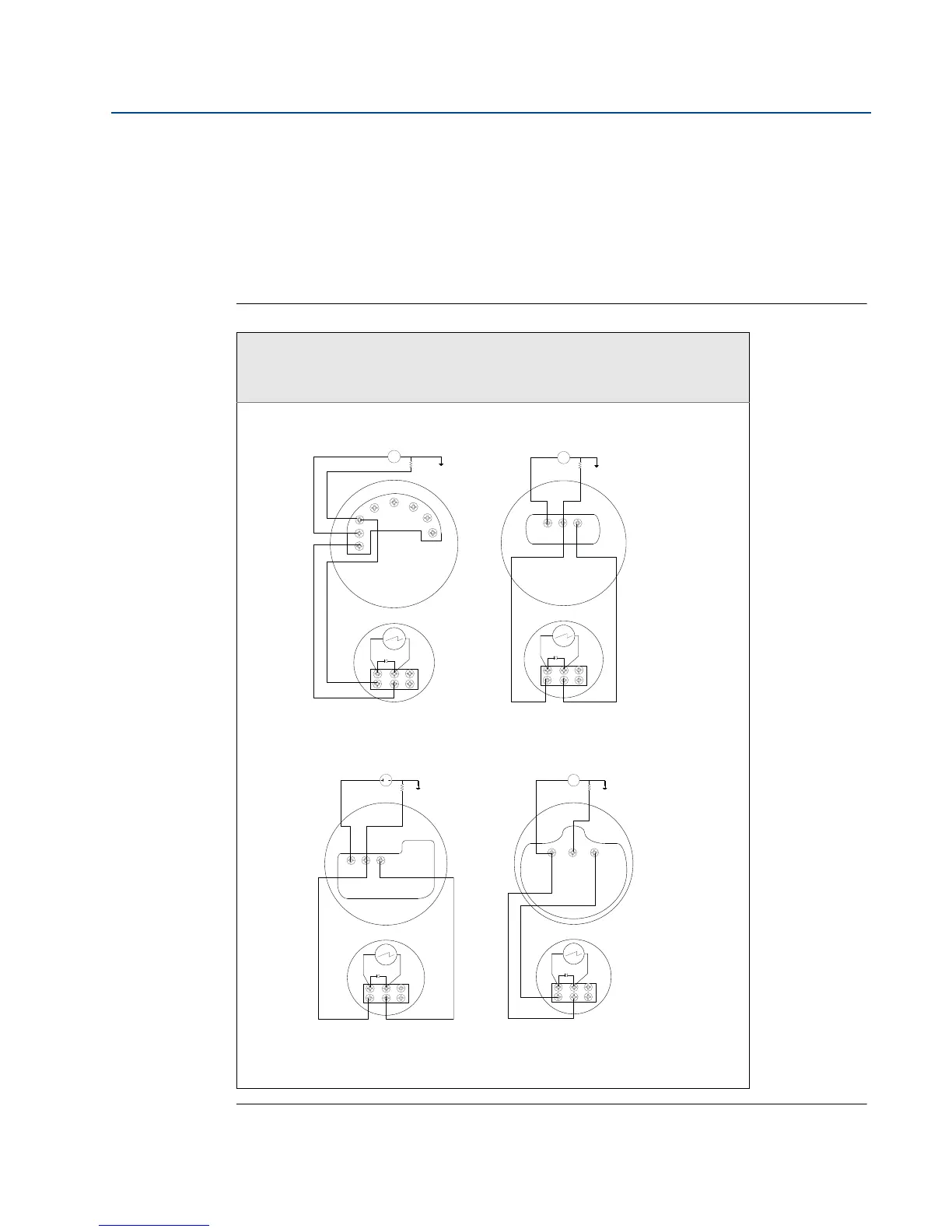
Figure 2-4. Rosemount 751 Parallel Wiring Diagrams
Parallel Wiring Diagrams for Rosemount 3144P Temperature
Transmitter
and Rosemount 2051, 3051C or 3051S Pressure Transmitters
Power Supply
Power Supply
751
4–20 dc Input Signal for
Rosemount 2051
4–20 mA dc Input Signal for
Rosemount 3144P
+
+
–
–
Optional Ground
Load
Resistor
T
2051
+
–
+
–
3144P
Optional Ground
Load
Resistor
–
+
T
751
+
–
Power Supply
Power Supply
4–20 dc Input Signal for
Rosemount 3051S
4–20 mA dc Input Signal for
Rosemount 3051C
+
+
–
–
Optional Ground
Load
Resistor
T
3051C
751
+
–
+
+
–
–
Optional Ground
Load
Resistor
T
3051S
751
+
–
3051C
4–20 mA dc Input Signal for
Rosemount 3051C