18
Reference Manual
00809-0100-4378, Rev CE
Appendix A: Reference Data
February 2014
Reference Data
A.5 Ordering information
Model Product description
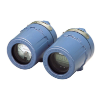
751 Remote Signal Indicator
Input signal
A 4–20 mA dc
B 10–50 mA dc (Not Available with LCD display)
C 40–200 mV dc (Not Available with LCD display)
Meter scale
M1 Linear Analog Meter, 0–100% Scale
M2 Square Root Analog Meter, 0–100% Flow
M6 Square Root Analog Meter, 0–10
M4
(1)
(1) May be reconfigured in the field.
Linear LCD display, 0–100% Scale
M7
(1)
Special Scale LCD display (specify range, mode, and engineering units)
M8
(1)
Square Root LCD display, 0–100% Flow
M9
(1)
Square Root LCD display, 0–10
Product certificates
NA No Approval Required
E2 INMETRO Flameproof
I2 INMETRO Intrinsic Safety
K2 INMETRO Flameproof, Intrinsic Safety
E3 NEPSI Flameproof
E5 FM Explosion-Proof
E6 CSA Explosion-Proof
E7 IECEx Flameproof
E8 ATEX Flameproof
I5 FM Intrinsic Safety and Non-incendive
I6 CSA Intrinsic Safety
I7 IECEx Intrinsic Safety
I8 ATEX Intrinsic Safety
N1 ATEX Type N Non-incendive
C6 CSA Intrinsic Safety, Non-incendive, and Explosion-proof approval combination
K5 FM Intrinsic Safety, Non-incendive, and Explosion-proof approval combination
Options
Mounting bracket
B Mounting Bracket for Flat Surface or 2-inch Pipe
Reducer
C Stainless Steel Reducer ¾- to ½-in. for Conduit Connection (See Figure 1 for reference.)
Bar code tag
BT Customer Specified Barcode Tag
Typical model number: 751 A M1 NA BC