9
Reference Manual
00809-0100-4378, Rev CE
Section 2: Installation
February 2014
Installation
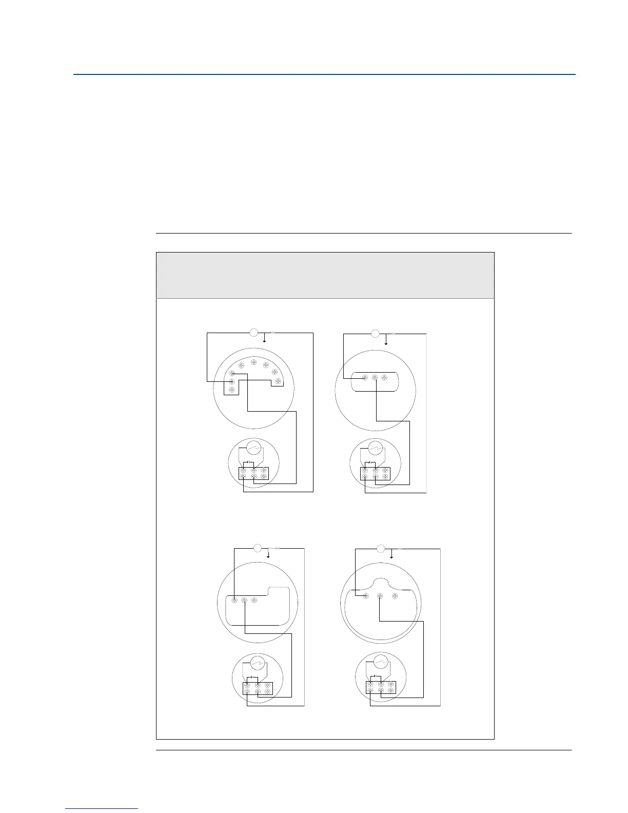
2.2 Wiring diagrams
Use the following wiring diagrams to wire the Rosemount 751 Field Signal Indicator, in series or
in parallel, with Rosemount transmitters. Use shielded cable for best results in electrically noisy
environments.
It is recommended that the 751 indicator be wired in a series configuration when the 4-20 mA
transmitter does not contain a test terminal. The 751 is designed so the analog or LCD display
can be removed from the housing without impacting the integrity of the 4-20 mA loop.
Removal of the entire 751 device from the series configuration will disrupt the loop.
Figure 2-3. Rosemount 751 Series Wiring Diagrams
Series Wiring Diagrams for Rosemount 3144P Temperature
transmitters and Rosemount 2051, 3051C, or 3051S Pressure
Transmitters
Power Supply
Power Supply
751
4–20 dc Input Signal for
Rosemount 2051
4–20 mA dc Input Signal for
Rosemount 3144P
+
+
–
–
Optional Ground
Load Resistor
T
2051
+
–
+
–
3144P
Optional Ground
Load Resistor
–
+
T
751
+
–
Power Supply
Power Supply
4–20 dc Input Signal for
Rosemount 3051S
4–20 mA dc Input Signal for
Rosemount 3051C
+
+
–
–
Optional Ground
Load Resistor
T
3051C
751
+
–
+
+
–
–
Optional Ground
Load Resistor
T
3051S
751
+
–