Reference Manual
00809-0100-4378, Rev CE
Section 2: Installation
February 2014
7Installation
Section 2 Installation
Assembly . . . . . . . . . . . . . . . . . . . . . . . . . . . . . . . . . . . . . . . . . . . . . . . . . . . . . . . . . . . . . . . . . . page 7
Wiring diagrams . . . . . . . . . . . . . . . . . . . . . . . . . . . . . . . . . . . . . . . . . . . . . . . . . . . . . . . . . . . . page 9
LCD display configuration . . . . . . . . . . . . . . . . . . . . . . . . . . . . . . . . . . . . . . . . . . . . . . . . . . . . page 11
2.1 Assembly
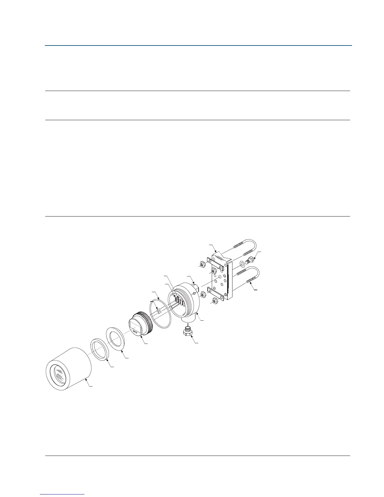
The Rosemount 751 Field Signal Indicator is comprised of the components shown in Figure 2-1.
The housing may contain an analog or LCD display. Both meters are independent of component
parts and are completely interchangeable. Both meters plug into the terminal screws on the
housing, as shown in Figure 2-1.
The meter subassembly contains the components shown in Figure 2-2.
Figure 2-1. Rosemount 751 Exploded View
A. Terminal Screws
B. Housing O-Ring
C. Field Wiring Terminals
D. Loop Protection Diode
E. Tapped Mounting Boss
F. Optional Mounting Bracket
G. Mounting Bolt with Washer
H. U-Bolt for 2-inch Pipe
I. Housing
J. Optional ¾ to ½-inch Conduit Reducing Bushing (if required)
K. Meter
L. Bushing
M. Foam Spacer
N. Housing Cover