Do you have a question about the Rosemount Oxymitter 4000 and is the answer not in the manual?
Manual updated for integrally mounted SPS 4000 Single Probe Autocalibration Sequencer.
Locks added for electronic housing covers throughout the manual.
Updated 'test gas' to 'calibration gas' and 'reference gas' to 'reference air'.
Included new symbols and product matrix information.
Troubleshooting section moved from Section VI to Section V.
Details warranty period, correction by repair or replacement, and exclusions.
To provide a comprehensive understanding of Oxymitter 4000 components, functions, installation, and maintenance.
Explains WARNINGS, CAUTIONS, and NOTES definitions and safety symbols.
Provides safety instructions for wiring and installation applicable to EU member states.
Lists typical system components and provides a table for recording part/serial/order numbers.
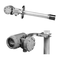
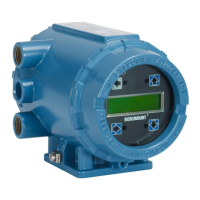
Describes the scope, system description, configuration options, and features of the Oxymitter 4000.
Details the capabilities and components of the SPS 4000 Single Probe Autocalibration Sequencer.
Describes the Model 751 display for remote indication of process variables.
Lists technical specifications for the Oxymitter 4000, including range, accuracy, and temperature limits.
Covers selecting the optimal location in the stack or flue for accurate oxygen analysis.
Provides instructions for electrical connections for the Oxymitter 4000 without the SPS 4000.
Details electrical connection procedures when the SPS 4000 is integrated.
Instructions for connecting reference air and calibration gas without the SPS 4000.
Details pneumatic connections for calibration gases and reference air with the SPS 4000.
Covers verifying mechanical installation and terminal block wiring before power-up.
Explains how to verify and set configuration switches (SW1, SW2) for operation.
Details the configuration modes for the logic I/O contact, for alarms or handshake signals.
Provides recommended settings for 4-20 mA signal and calibration procedures.
Describes the startup display, operating display, and error indication sequence.
Explains normal operation, diagnostic LEDs, calibration indicators, and test points.
Details the function of diagnostic alarm LEDs and how they indicate system errors.
Indicates when the system recommends a calibration procedure.
Describes the function of the INC, DEC, and CAL keys for calibration and monitoring.
Provides guidance on identifying and isolating faults, including grounding and ESD precautions.
Explains how fault conditions are indicated by diagnostic LEDs and error messages.
Describes the logic I/O contact usage for alarms and autocalibration handshake signals.
Troubleshooting steps for an open thermocouple fault indicated by the HEATER T/C LED.
Troubleshooting steps for a shorted thermocouple fault indicated by the HEATER T/C LED.
Troubleshooting steps for a reversed thermocouple wiring fault indicated by the HEATER T/C LED.
Troubleshooting steps for an open heater fault indicated by the HEATER LED.
Troubleshooting steps for a high high heater temperature fault indicated by the HEATER LED.
Troubleshooting steps for a high case temperature fault indicated by the HEATER LED.
Troubleshooting steps for a low heater temperature fault indicated by the HEATER LED.
Troubleshooting steps for a high heater temperature fault indicated by the HEATER LED.
Troubleshooting steps for a high cell mV fault indicated by the O2 CELL LED.
Troubleshooting steps for a bad cell fault indicated by the O2 CELL LED.
Troubleshooting steps for an EEPROM corrupt fault indicated by the O2 CELL LED.
Troubleshooting steps for an invalid slope fault indicated by the CALIBRATION LED.
Troubleshooting steps for an invalid constant fault indicated by the CALIBRATION LED.
Troubleshooting steps for a last calibration failed fault indicated by the CALIBRATION LED.
Guidance for troubleshooting SPS 4000 faults, focusing on calibration gas flow issues.
Identifies calibration methods and procedures for maintaining and servicing the Oxymitter 4000 and SPS 4000.
Details calibration gases, flow rates, and three calibration methods: automatic, semi-automatic, and manual.
Describes initiating semi-automatic calibration via keypad, IMPS 4000, HART, AMS, or remote contact.
Explains the procedure for performing manual calibration directly at the Oxymitter 4000 site.
Step-by-step instructions for removing and replacing the Oxymitter 4000 unit.
Procedures for replacing electronic components like the entire electronics assembly, terminal block, or fuse.
Guidance on replacing the probe assembly, excluding electronics, if performance issues persist.
Instructions for replacing the heater strut assembly.
Procedure for replacing the oxygen sensing cell, emphasizing troubleshooting before replacement.
Detailed steps for replacing the ceramic diffusion element, including cement application.
Describes maintenance for SPS 4000, including fuse and board replacement procedures.
Introduces the HART Communicator as an interface device for HART-compatible instruments.
Explains how to connect the HART Communicator to the 4-20 mA analog output signal line.
Describes interfacing the HART Communicator with a personal computer using AMS software.
Details how the HART Communicator can be operated both off-line and on-line.
Lists the ten configurable modes for the Oxymitter 4000 logic I/O output via HART/AMS.
Provides a menu tree specific to HART Communicator applications on the Oxymitter 4000.
Step-by-step procedure for performing an O2 calibration using the HART Communicator.
Procedure for specifying a time interval for automatic Oxymitter 4000 calibration via HART.
Lists part numbers and descriptions for various probe assemblies and components.
Lists part numbers for electronic assemblies, housings, keypads, and termination blocks.
Lists part numbers for SPS 4000 components like gaskets, valves, boards, and solenoids.
Lists part numbers for calibration gas bottles and flow regulators.
Details steps for securing return authorization, packing, and shipping defective equipment.
Describes the HART handheld communicator for diagnostics, configuration, and calibration.
Explains AMS software for communicating with HART devices from a computer.
Describes By-Pass Packages designed for high temperatures and process sampling.
Details the IMPS 4000 sequencer for automatic and semi-automatic calibration routines.
Describes the SPS 4000 for automatic or on-demand Oxymitter 4000 calibrations.
Highlights convenient and portable O2 calibration gas and service kits.
| Category | Transmitter |
|---|---|
| Manufacturer | Rosemount |
| Product Name | Oxymitter 4000 |
| Measurement Type | Dissolved Oxygen |
| Measurement Principle | Electrochemical |
| Output Signal | 4-20 mA |
| Communication Protocol | HART |
| Measurement Range | 0 to 20 mg/L |
| Pressure Range | 0 to 100 psig |
| Power Supply | 24 VDC |
| Enclosure | NEMA 4X |
