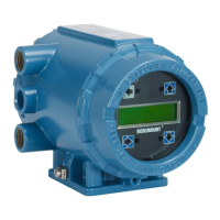
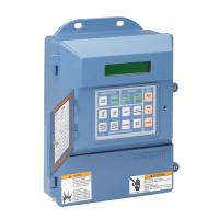
Do you have a question about the Rosemount 3144 and is the answer not in the manual?
Explains how to use the manual effectively to understand product installation, operation, and maintenance.
Introduces the Model 3144 and 3244MV Smart Temperature Transmitters, their capabilities, and HART communication.
Details compatibility requirements for HART communicators and software revisions with the transmitters.
Provides an overview of the installation process, including flowchart, drawings, and considerations.
Highlights critical safety precautions necessary for personnel performing installation operations.
Lists specific warnings regarding potential hazards like explosions, leaks, and electrical shock during installation.
Explains the process of commissioning the transmitter, either before or after physical installation.
Discusses general factors to consider for proper transmitter installation and operation.
Details electrical requirements and best practices to prevent errors due to noise and resistance.
Specifies the minimum DC power supply requirements for transmitter operation and communication.
Provides instructions for connecting the transmitter to the loop using field wiring practices.
Explains how to correctly connect the power and current loop wiring to the transmitter terminals.
Provides recommendations and techniques for grounding the transmitter and its wiring.
Discusses protection against electrical surges and transients induced by external sources.
Covers connecting multiple transmitters to a single power supply and considerations for reliability.
Explains the function and location of the failure mode and transmitter security jumpers.
Details the purpose and settings of the failure mode jumper for alarm behavior.
Describes the function of the security jumper to prevent unauthorized configuration changes.
Provides step-by-step instructions for altering the position of the jumpers.
Illustrates correct input connections for various sensor types to the transmitter terminals.
Specific connection details and considerations for RTD and Ohm sensor inputs.
Specific connection details and considerations for Thermocouple and Millivolt inputs.
Discusses mechanical aspects of installation, including mounting and access.
Covers mounting options and recommendations for the transmitter, including pipe and panel mounts.
Addresses the need to ensure adequate access to the transmitter after installation.
Outlines factors related to the installation environment, such as temperature and humidity.
Explains how ambient temperature affects transmitter accuracy and performance.
Provides guidance for installing the transmitter in humid or corrosive environments to prevent moisture accumulation.
Details installation requirements and guidelines for transmitters used in hazardous areas.
Provides a step-by-step guide for the physical installation of the transmitter.
Illustrates a common transmitter installation configuration for North America.
Illustrates a common transmitter installation configuration for Europe.
Describes the installation process when using the transmitter with a HART Tri-Loop converter.
Details the specific commissioning steps for the transmitter when used with the HART Tri-Loop.
Introduces information needed to configure and format the transmitter on-line or off-line.
Highlights safety precautions required during on-line transmitter operations.
Lists specific warnings related to potential hazards during on-line operations.
Explains the necessity of setting the process loop to manual before data operations.
Guides on reviewing factory-set configuration data for accuracy and application compatibility.
Details how to review transmitter configuration parameters for accuracy and compatibility.
Covers checking digital output parameters to ensure proper transmitter operation.
Explains how process variables provide transmitter output and can be remapped.
Describes essential configuration steps required for transmitter operation.
Guides the user on selecting the correct input sensor type for the transmitter.
Explains how to set the primary variable engineering units for the transmitter output.
Details how to set the 4 and 20 mA points to optimize transmitter performance.
Covers advanced configuration settings and options for the transmitter.
Explains how to set the electronic filter to match plant AC power frequency to reduce noise.
Guides on setting the transmitter's terminal temperature units for ambient indication.
Covers viewing or changing range values, sensor percentage, and sensor damping.
Explains how to view the analog output signal, alarm settings, and initiate a loop test.
Details how to disable sensor matching or other special sensor configurations.
Covers changing HART multidrop address, preambles, burst mode, and options.
Explains how to set meter options for display customization, including engineering units.
Covers viewing the high and low alarm and saturation values for the transmitter.
Explains how to change the transmitter response time to smooth output variations.
Details configuring the transmitter to measure and display the differential temperature between two inputs.
Guides on configuring the transmitter to measure and display the average temperature of two inputs.
Explains configuring automatic sensor redundancy, where Sensor 2 becomes primary if Sensor 1 fails.
Covers configuring alerts for when sensor differences exceed a user-defined limit.
Lists transmitter configuration variables like Tag, Descriptor, and Serial Numbers accessible via HART.
Explains using the Tag variable for easy identification of transmitters in multi-transmitter environments.
Details the Descriptor variable for longer, user-defined transmitter identification.
Covers using the Message variable for specific, user-defined transmitter identification.
Explains the Date variable for tracking the last revision of configuration information.
Provides a location to list the serial number of the attached sensor for identification.
Lists the serial number for the second sensor on the Model 3244MV.
Covers commands for transmitter diagnostics, testing, and measurement functions.
Explains initiating an extensive diagnostics routine beyond continuous monitoring.
Guides on verifying the transmitter output, loop integrity, and connected devices.
Details enabling or disabling the Active Calibrator Mode for sensor trimming.
Explains how calibration increases the precision of the measurement system.
Helps the user choose the appropriate trim procedure based on calibration needs.
Covers calibrating the sensor and transmitter together using a site-standard input source.
Explains the procedure to enhance temperature measurement accuracy using Callendar-Van Dusen constants.
Guides on adjusting the transmitter's digital-to-analog signal conversion for precision.
Covers using process inputs to set the 4 and 20 mA values based on a chosen scale.
Explains connecting multiple transmitters to a single communications line.
Introduces transmitter diagnostics and general maintenance information.
Highlights safety precautions required during maintenance procedures.
Lists specific warnings related to potential hazards during maintenance.
Guides on verifying transmitter hardware and process connections for troubleshooting.
Covers general maintenance tasks for transmitter hardware, emphasizing modular design.
Explains the use of test terminals for in-process checks and measurements.
Guides on how to determine if the sensor is faulty and how to test it.
Details the procedure for safely taking apart the transmitter's electronics housing.
Provides step-by-step instructions for reassembling the transmitter's electronics housing.
Outlines the process and contact information for returning failed transmitters or parts for service.
Lists detailed functional, performance, and physical specifications for the transmitters.
Details input, output, isolation, and power supply specifications.
Covers temperature limits, humidity, turn-on time, accuracy, and stability.
Includes details on conduit connections, materials of construction, weight, and enclosure ratings.
Provides diagrams showing transmitter dimensions, jumper locations, and meter faceplate.
Contains input options, accuracy data, and ambient temperature effects for sensors.
Lists model numbers, options, housing types, and part codes for ordering transmitters.
Provides a comprehensive list of replacement parts for the Model 3144 and 3244MV transmitters.
Explains the algorithm monitoring input signals and detecting conditions like open sensors.
Details the feature for guarding against process temperature spikes and open sensor conditions.
Describes the available options that enhance transmitter operation and installation.
Highlights safety precautions related to the installation and use of transmitter options.
Lists critical warnings associated with transmitter options.
Allows specifying data like date, descriptor, and message for transmitter configuration.
Orders the transmitter trimmed to a specific RTD calibration schedule for enhanced accuracy.
Specifies that the transmitter be verified at five analog and digital output calibration points.
Details the calibration certificate shipped with the transmitter, including calibration data points.
Allows ordering the transmitter trimmed to a non-standard sensor type.
Describes mounting brackets for direct sensor mounting or remote installation.
Specifies how the transmitter will be assembled to a sensor (wired/unwired, tight).
Provides an auxiliary grounding point for the transmitter housing.
Specifies calibration to a 50 Hz line voltage filter, recommended for European installations.
Sets transmitter linear output and alarm levels to comply with NAMUR standards.
Helps prevent transmitter damage from transients induced on the loop wiring.
Selects configuration for automatic redundancy where Sensor 2 becomes primary if Sensor 1 fails.
Configures average temperature output, alerts for sensor differences, and hot backup.
Configures Sensor 1 as primary and Sensor 2 as secondary for measuring separate temperatures.
Configures the differential temperature of two process temperatures as the primary variable.
Configures the average measurement of two different process temperatures.
Provides local indication of transmitter output and abbreviated diagnostic messages.
Guides on the procedure for installing the LCD meter on a transmitter.
Step-by-step instructions for installing the LCD meter and configuring the transmitter.
Explains the abbreviated diagnostic messages displayed on the LCD meter for troubleshooting.
Describes additional features and enhancements available in improved transmitter models.
Compares revision numbers and feature differences between improved and previous transmitter models.
Introduces the HART communicator's keypad, connections, menu structure, and fast-key sequences.
Highlights safety precautions required when using the HART communicator.
Lists specific warnings related to potential hazards when using the HART communicator.
Displays the HART communicator menu tree for use with the Model 3144 and 3244MV transmitters.
Introduces the SMART FAMILY Interface as a common communication link for Rosemount instruments.
Highlights safety precautions required when using the Model 268 SMART FAMILY Interface.
Lists specific warnings related to potential hazards when using the Model 268 Interface.
Details how to connect the Model 268 Interface to a transmitter loop.
Covers the basic features of the Model 268, including keys and display functions.
Explains the functions of the dedicated keys on the Model 268 Interface.
Contains transmitter hazardous location installation drawings to maintain certified ratings.
Emphasizes marking approval labels to distinguish used from unused approval types.
| Type | Temperature Transmitter |
|---|---|
| Communication Protocol | HART |
| Operating Temperature | -40 to 85 °C (-40 to 185 °F) |
| HART Protocol Version | HART 7 |
| Housing Material | Aluminum or Stainless Steel |
| Ambient Temperature Range | -40 to 85 °C (-40 to 185 °F) |
| Input | RTD, Thermocouple, mV, ohm |
| Measurement Range | Depends on sensor type |
| Output Signal | 4-20 mA with HART |
| Enclosure Rating | Type 4X, IP66 |
| Sensor Type | RTD, Thermocouple |
| Process Connection | 1/2" NPT |
| Electrical Connection | 1/2" NPT or M20 x 1.5 |
