6-7
Options
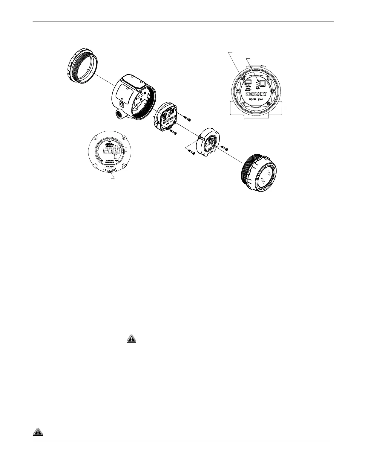
Figure 6-3. Transmitter and Meter
Exploded View.
Installing the Meter Transmitters ordered with the LCD meter option (Option Code M5) are
shipped with the meter installed. After-market installation of the meter
on a conventional Model 3144 or 3244MV transmitter requires a small
instrument screwdriver and the meter kit, which includes:
• LCD meter assembly
• Extended cover with cover O-ring in place
• Captive screws (quantity 2)
• 6-pin interconnection header
Use the following procedure to install the meter. Once the meter is
installed, configure the transmitter to recognize the meter option. Refer
to “Meter Settings” on page 3-6.
Installation Procedure 1. If the transmitter is installed in a loop, then secure the loop and
disconnect the power.
2. Remove the cover from the electronics side of the transmitter. Do
not remove the transmitter covers in explosive atmospheres if the
circuit is alive.
3. Remove the failure mode jumper and the plastic insulating pins
from the six-pin socket on the face of the electronics module.
Refer to Figure 6-3.
4. Ensure that the transmitter security mode jumper is set to the
Off position. If transmitter security is On, then you will not be
able to configure the transmitter to recognize the LCD meter.
LCD Meter
Electronics
Module
Housing
Cover
Security Jumper
Failure Mode Jumper
(without a Meter Installed)
Failure Mode Jumper
(with a Meter Installed)
3144-2352A01D, 0000A03B, 0200G01A
See “Safety Messages” on page 6-1 for complete warning information.