Control Panel Overview
This chapter provides a basic introduction to the control
panel, including an overview of the different areas on
the control panel, using the menu system, as well as an
introduction to the various ports, and video buses.
Control Panel Areas
Each Carbonite control panel is made up of a number of
distinct areas that control different aspects of the
switcher. Some of these areas may vary in size or
function, depending on the control panel you have.
KEY/AUX/CUSTOMCONTROL
TRANSITION2
PROGRAM
PRESET
SHOW
ALPHA
KEY
PV
AUTO
SELECT
SELF
KEY
CHR
KEY
DVE
KEY2
SEL
KEY1
SEL
KEY3
SEL
KEY4
SEL
AUX
2
AUX
1
AUX
3
AUX
4
AUX
6
AUX
5
AUX
7
AUX
8
BANK
2
BANK
1
BANK
3
BANK
4
BANK
6
BANK
5
BANK
7
BANK
8
BANK
2
BANK
1
BANK
3
BANK
4
BANK
6
BANK
5
BANK
7
BANK
8
MLE
2
MLE
1
USER
1
USER
2
KEY/AUX/CUSTOMCONTROL
PROGRAM
PRESET
STORE
7 8 9
RECALL
BKGD KEY1 KEY2 KEY 3 KEY4
DISS WIPE DVE MEDIA USER
BKGD KEY1 KEY2 KEY 3 KEY4
DISS WIPE DVE MEDIA USER
PGM
4 5 6
EFF
RATE
MEM
AI
1 2 3
MLE
RATE
EFF
DISS
BANK
0
ENTER
KEY
RATE
STORE
7 8 9
RECALL
PGM
4 5 6
EFF
RATE
MEM
AI
1 2 3
MLE
RATE
EFF
DISS
BANK
0
ENTER
KEY
RATE
SHOW
ALPHA
KEY
PV
AUTO
SELECT
SELF
KEY
CHR
KEY
DVE
KEY2
SEL
KEY1
SEL
KEY3
SEL
KEY4
SEL
AUX
2
AUX
1
AUX
3
AUX
4
AUX
6
AUX
5
AUX
7
AUX
8
MLE
2
MLE
1
USER
1
USER
2
PUSH PUSH PUSH
MLE1
STORE
MLE1
RECALL
MLE2
STORE
MLE2
RECALL
LOCK
HOME
CC
UP
MENU
BACK
NEXT
(SHIFT)
KEY4
CUT
KEY3
CUT
KEY2
CUT
KEY1
CUT
KEY4
AUTO
KEY3
AUTO
KEY2
AUTO
KEY1
AUTO
ROLL
CLIP
CUT
AUTO
TRANS
TRANSITION1EFFECTSMEMORY 1
EFFECTSMEMORY 2
ROLL
CLIP
CUT
AUTO
TRANS
KEY4
CUT
KEY3
CUT
KEY2
CUT
KEY1
CUT
KEY4
AUTO
KEY3
AUTO
KEY2
AUTO
KEY1
AUTO
1 318
7
16
7
8
9
10
9
10
12
13
14
1417
17
11
12
13
11
4
5
5
6
6
15
16 8
Figure 4: C2X Control Panel
STATUS OPTIONS SYSTEM REF CONFIG
RESET
AUX
PGM
AUX
PREV
AUX
CLN
USER PERS SAVE LOAD
PUSH PUSH PUSH
KEY/AUX
PROGRAM
PRESET
BLACK/
MATTE
INPUT1/
INPUT9
INPUT2/
INPUT10
SHIFTINPUT6INPUT5
INPUT4/
INPUT12
INPUT3/
INPUT11
INPUT8/
MEDIA2
INPUT7/
MEDIA1
KEY3
TRANS
KEY2
TRANS
KEY3KEY2
AUX
1
KEY2
SEL
KEY1
SEL
KEY3
SEL
AUX
2
AUX
3
STORE RECALL
MENU NEXT
AUTO
SEL
CHR
KEY
BKGD KEY 1
KEY1
TRANS
DISS WIPE DVE
CUT
AUTO
TRANS
DVE
31
9
11
12
13
14
4
5 6
15
7
Figure 5: C10 Control Panel
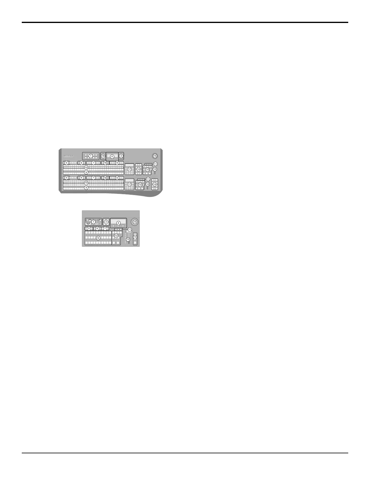
1.
Pattern/Menu Selection Buttons — These buttons
are used to select a pattern for a wipe transition, or
to access switcher menus. The C10/C1 control panels
have the name of the menus below the pattern
button.
2.
Custom Control Command Buttons — These
buttons are used to start, stop, edit, and navigate
through custom controls.
3.
Menu Navigation and Memory Control Buttons
— These buttons are used to access switcher menus,
move back and forth between menus. On the C10,
these buttons are also used to store and recall
switcher memories.
4.
Main Display and Selection Knobs — The three
selection knobs are used to adjust and select various
menu items or values. The knobs are rotated to
choose a value, and pressed to make a selection. The
main display shows the menu system of the switcher.
5.
Key Type Buttons — These buttons are used to
choose the type of key you want to use. Use these
buttons with the key select buttons to select the
keyer, and the type of key you want to use.
6.
Key Select Buttons — These buttons are used to
choose which keyer is selected. The key type buttons
and key bus follow the selected keyer.
7.
Aux Bus Select Buttons — These buttons are used
to choose which aux bus is selected. The aux bus
follows the selected aux bus.
8.
Custom Control Bank Select Buttons — These
buttons are used to choose which custom control
bank is selected. The custom control bus follows the
selected custom control bank.
9.
Video Source Buses — These buses are broken into
the Preset, Program, and Key/Aux/Custom Control
buses. The Preset bus is the bottom row of source
buttons and selects the video source that will be
taken on-air with the next background transition.
The Program bus is the middle row of source buttons
and selects the video source that is currently on-air
on the background. The Key/Aux/Custom Control
bus is the top row of source buttons and selects the
video source that is chosen on the selected keyer or
aux bus, or the custom control that is chosen on the
selected custom control bank.
10.
Mnemonic Displays — The mnemonic display
shows the name of the source assigned to the source
button directly below it. The mnemonic
display-name and color for each video source can
be adjusted.
11.
On-Air Lights — These lights glow red to show
which keyers are currently on-air.
12.
Transition Area — These buttons are used to select
which video source buses will be included in the
next transition and what type of transition will be
performed. The Cut and Auto Trans buttons are used
to perform transitions. The user button on the
C2S/C2X/C3S/C3X control panel is not
implemented at this time.
13.
Manual Transition Fader Bar — The fader is used
to manually control the rate of a transition. What is
being transitioned, and the type of transition, are
controlled from the Transition Area.
14.
Keyer Transitions Buttons — These buttons are
used to perform cuts or auto transitions on keys
directly, without having to include them as part of
the next transition.
15.
Positioner — The positioner is used to control some
wipe, border, and wash parameters, as well as some
external devices.
16.
ME Selection Buttons — These buttons are used
to assign the control panel row to an ME, MiniME
™
,
or MultiScreen.
17.
Effects Memory Area — This area is used to store
and recall memories on the assigned ME, and to
14 • Control Panel Overview — Carbonite Operation Manual (v13.0)

 Loading...


