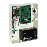
AC-215 Single and Double Door Access Control Unit
Hardware Installation Guide
13
C
C
o
o
m
m
m
m
u
u
n
n
i
i
c
c
a
a
t
t
i
i
o
o
n
n
s
s
Communication lines are used to upload and download information between the ACU and the
AxTrax AS-525 software. Communication between the ACU and PC is displayed by the
system’s two LEDs.
The RX LED flashes when the controller receives data
The TX LED flashes when the controller transmits data
The ACU address is defined in the AxTrax™ AS-525 software. For successful
communications, the dipswitch must be defined with the same address.
There are three connection modes:
Serial
RS232
RS485
Modem
LAN
Serial Connection
The PC Serial Port controlling the ACU is assigned in the Network Properties in the AxTrax
AS-525 software. By default the default is set to 9600 for direct connection to the PC using the
standard RS232 interface.
RS232 Connection
ACU DB9 Connector DB25 Connector
GND Pin 5 Pin 7
Tx Pin 2 Pin 3
Rx Pin 3 Pin 2
DTR Pin 4 Pin 20
The RS232 connection can only be used for one ACU. The distance between the PC and
ACU can be no more than 150 feet (50 meters). If the baud rate is increased to 57600 the
distance can be up to 30 feet (10 meters). J1 must be in the RS232 position to select the
RS232 communication.

 Loading...