EasyManuals Logo

Rosslare AC-215IP User Manual

Rosslare AC-215IP
37 pages
To Next Page IconTo Next Page
To Previous Page IconTo Previous Page
Page #34 background imageLoading...
Page #34 background image
Communications
34 AC-215IP Hardware Installation Manual
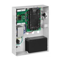
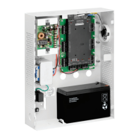
6.3.4 AC-215IP Panel Connections
1. Connect a 9 VDC adapter to the second MD-N33. Make sure that the
power LED (Red) is on.
2. Connect the MD-N33's RJ11 jack to the telephone wall mount using the
telephone cable.
3. Connect the MD-N33 DB9 female jack to the MD-14 DB9 female jack.
4. Connect the AC-215IP RS-485 outlet to the MD-14 4 wires cable. Make
sure the J1 switch (on the AC-215IP) is set to RS-485 Mode.

Table of Contents

Questions and Answers:

Question and Answer IconNeed help?

Do you have a question about the Rosslare AC-215IP and is the answer not in the manual?

Rosslare AC-215IP Specifications

General IconGeneral
BrandRosslare
ModelAC-215IP
CategoryIP Access Controllers
LanguageEnglish

Related product manuals