Wiring
12 AY-U920BT-US Installation and User Manual
4. Wiring
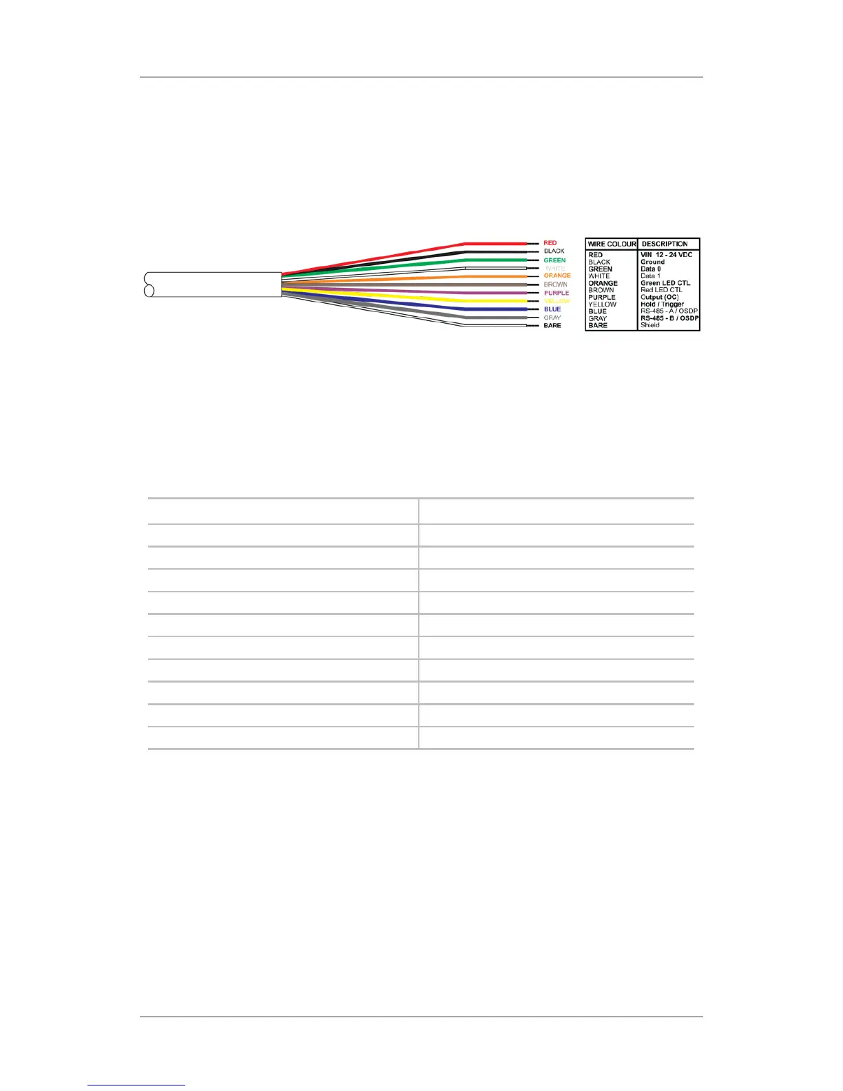
The units are supplied with a 5 m (16.4 ft) 10-conductor pigtail with exposed
wires coated with solder (see Figure 5).
Figure 5: Wiring Colors
To connect the unit as a reader to an access control unit:
1. Select the appropriate connections according to Table 1.
2. Prepare the controller cable by cutting its jacket back about 3 cm (1¼")
and strip the insulation from the wires about 1.3 cm (½").
3. Splice the reader’s pigtail wires to the corresponding controller wires and
cover each joint with insulating tape.
Table 1: Wiring the Unit as a Reader to a Control Panel
Wire Color Output
Red Power
Black Ground
Green Data 0 / Data / C2
White Data 1 / Clock / C1
Orange Green LED Control
Brown Yellow LED Control
Purple OC Output*
Yellow Hold/Trigger Control
Blue RS-485 - A / OSDP**
Gray RS-485 - B / OSDP**
* for future use
** RS-485 is used for firmware update.
 Loading...