INSTALLATION MANUAL
AIRCRAFT ENGINES
page 18 - 2
Initial issue, May 01/99
Effectivity: 447 UL SCDI, 503 UL DCDI, 582 UL DCDI /mod. 99
d00328
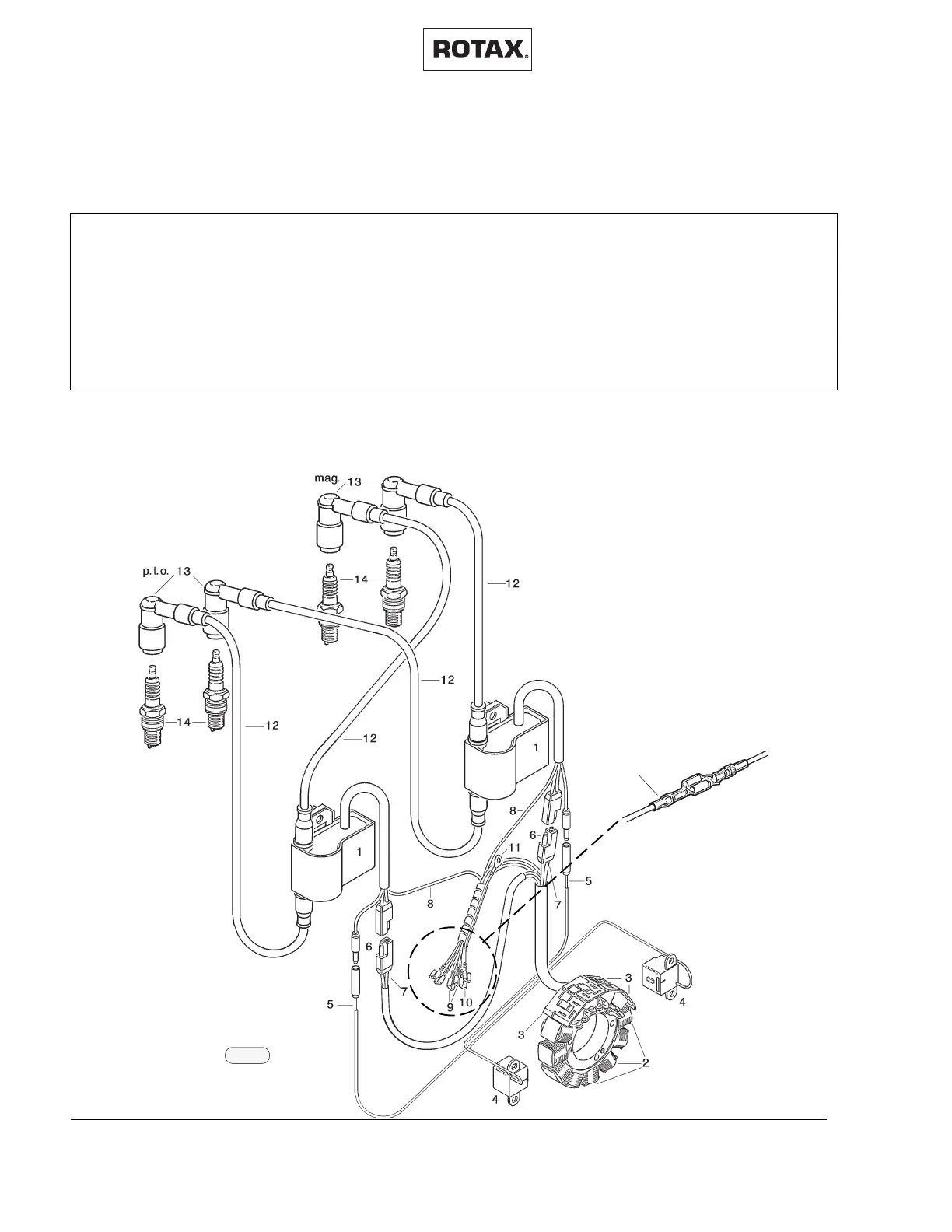
18.3) Wiring diagram:
◆ NOTE: When replacing wiring on the ignition system, connections
must be as per wiring diagram below.
1 Electronic box 6 charging cable, green 10 rev.counter cable, gray
2 eight lighting coils 7 charging cable, white 11 mass cable, brown
3 four charging coils 8 shorting cables, black/yellow 12 ignition cables
4 pickup 9 lighting cables, yellow- 13 spark plug connectors
5 trigger cable, red yellow/black 14 spark plugs
15 shrink tube
After installing, all the connections must be protected with the supplied shrink
tubing.
◆ NOTE: Wiring diagram shows DCDI ignition.
02822
15
02821
fig. 38
 Loading...