d06703.fm
SI-912 i-024
SI-915 i-006
SERVICE INSTRUCTION
03 July 2019 76-10-00
Initial Issue Page 9 of 18
Copyright - BRP-Rotax GmbH & Co KG. All rights reserved.
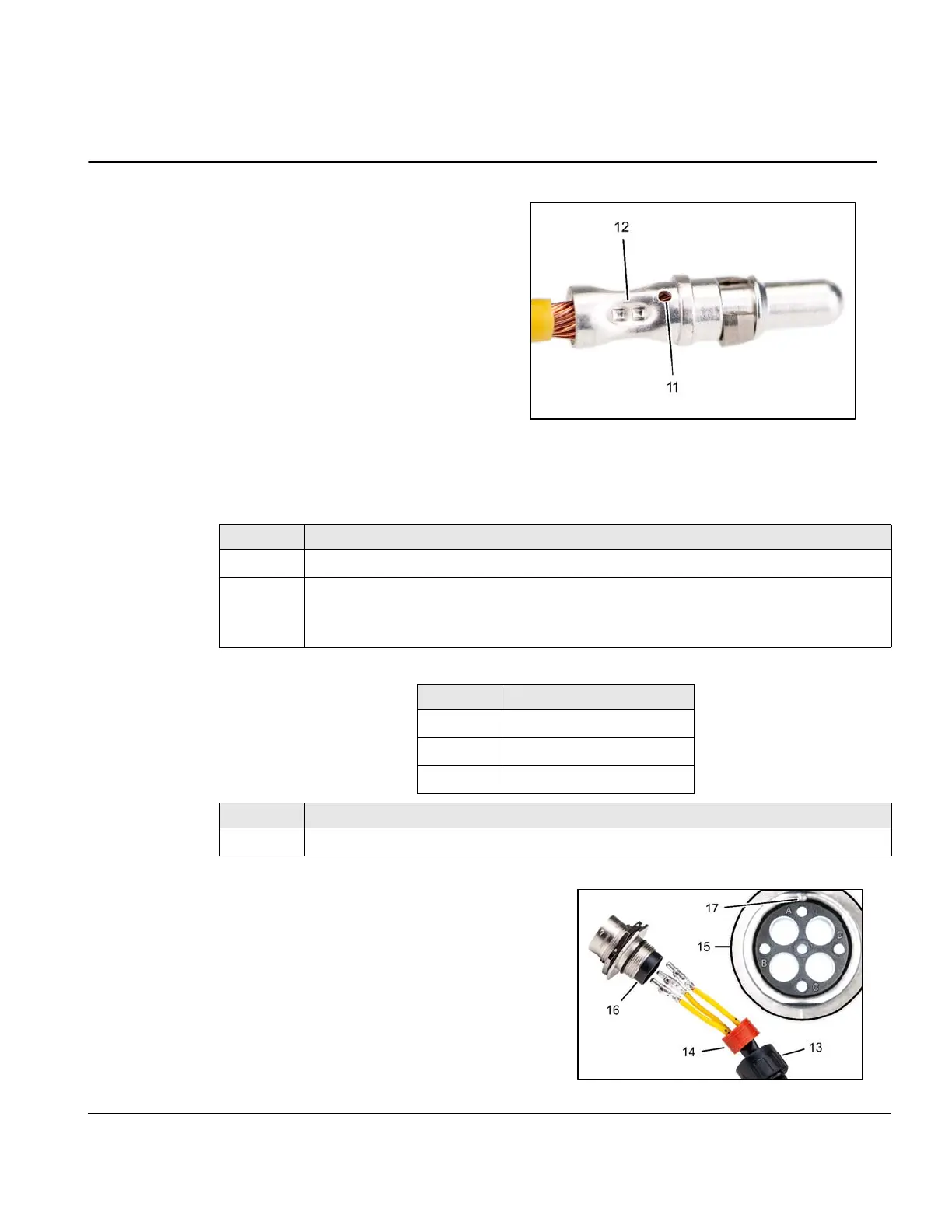
Fig. 6
Assembly of the connector housing Amphenol® part no. 864595
Place numbered wires in the following alphabetical positions:
Fig. 7
Step Procedure
1 Place rear connector screw cap over wires (13).
2
Push connector pins and wires through round rubber seal (14).
NOTE: New connector positions are marked A through D (15), whereas wires
were marked 1 through 4 from old connector positions.
Wire Connector position
1A
2B
3C
Step Procedure
3 Slide plastic sleeve (16) into the back of connector housing, aligning the keyway (17).
11 Witness hole
12 Crimp-barrel
13 Screw cap
14 Rubber seal
15 Position letter
16 Sleeve
17 Key

 Loading...


