AC-2000 | 8.10/8.11 10
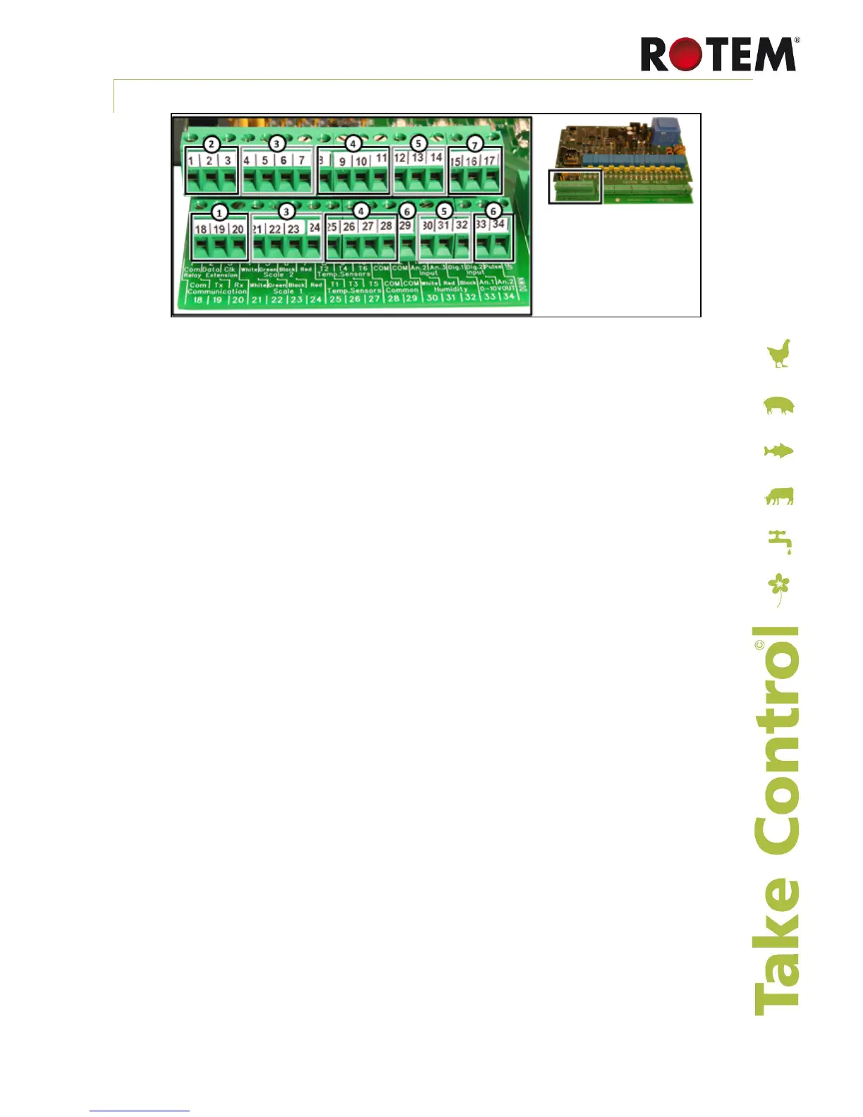
4.2.4 AC-2000 Plus Terminals
1. Communications: Three terminal blocks for PC communication using the optional
multiplexor, MUX-2.
o RX (20): Receive into AC-2000 PLUS. With multiple controls, connect all the RX pins
together. Connect to TX at Multiplexor only.
o TX (19): Transmit from AC-2000 PLUS With multiple controls, connect all the TX pins
together. Connect to RX only at Multiplexor only.
o COM (18): Ground reference for communications. Do not connect shields to this pin.
Connect to COM at multiplexor also.
2. Relay Extension: Com (1) - The relay extension box such as the REB-8 may be located up
to 10 feet from the AC-2000 PLUS. Do not connect the shield to this terminal. Connect the
shield to earth ground only at one end of the cable to avoid ground loops.
o Data (2): This line carries data to the relay extension.
o Clk (3): This line carries a clocking signal for use by the relay extension.
3. Not used.
4. 6 Temperature Sensors (8, 9, 10, 25, 26, 27): The temperature sensor is a 2 wired black
shielded cable thermistor (RTS-2). Connect one wire to the temperature sensor terminal and
the other to common (11, 28) *Polarity does not matter.
5. Analog Inputs:
o Humidity Sensor (30, 31, 32): Connect according to wire colors (White, Red, Black).
o An.2 (13): Humidity Outside Humidity input. Connect the white wire of the Humidity sensor
to An.2 and the red and black together with the Humidity input red and black.
o An.3 (14): Pressure sensor (Connect + red wire to An.3 and Black – wire to Common).
6. Analog Outputs:
o An.1 (33): 0 to 10V- Light Intensity control signal
o An.2 (34): 0 to 10V- Variable speed control signal
o COM (29): Connect the common wire of An.1 & 2 to terminal 29
7. Digital Inputs:
o Dig 1 (15): Feed overtime alarm input or wind direction selection
o Dig 2 (16): Feed counter
o Dig 3 (17): Water meter