AC-2000 | 8.10/8.11 20
Ventilation Level Ventilation Groups On Minutes Off Minutes Diff Var Var #2
15 1 2 3 4 0 0 0 0 0 0 0 0 1.0 0.0 0 0 0
16 1 2 3 4 0 0 0 0 0 0 0 0 1.0 0.0 1.0 0 0
17 1 2 3 4 5 0 0 0 0 0 0 0 1.0 0.0 2.0 0 0
18 1 2 3 4 5 6 0 0 0 0 0 0 1.0 0.0 3.0 0 0
19 1 2 3 4 5 6 7 0 0 0 0 0 1.0 0.0 4.0 0 0
20 1 2 3 4 5 6 7 0 0 0 0 0 1.0 0.0 4.0 0 0
The AC-2000 increases the fan power as ventilation requirements rise. The increments should be
proportional from level to level. This means that the ventilation increases about 50% to 100% at each level.
For example, at Level One a single fan is set to 0.5 minutes on and 9.5 minutes off. At Level Two, if you set
the fan to 1.0 minute on and 9.0 minutes off, there is a 100% increase. At a much higher level, such as
ventilation level 15, an increase from 4 fans to 6 fans represents a 50% increase in fan power. Please
review the example ventilation tables for this principle.
The ventilation table, Menu 92, defines the fan powered ventilation levels for the poultry house. This
includes variable speed, timer and on/off fans for up to 20 levels of ventilation. At each ventilation level, a
cycle timer can run the highest numbered fan group used at that level. With no values in the timer on and
off fields, or only an off time or only an on time, the AC-2000 defaults to constant on operation.
Due to limited display size, the AC-2000 shows only the on-off timer or the variable speed setting at each
level. Use Menu 91, item 4 to select which setting the AC-2000 shows. However, both settings remain in
memory.
Since air movement provides a cooling effect, the AC-2000 provides a temperature differential at each
level. This is particularly important in tunnel ventilation, where the cooling effect can be (–12) °C. The
AC-2000 waits until the target temperature plus the differential before using that ventilation level.
NOTE: The ventilation table coordinates with the curtain table. For natural ventilation, one should
regard the curtain table as part of the ventilation table. The two tables together serve as one
larger table.
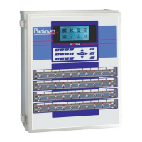
5.3 Relay Layout (Menu 93)
Relay Code NO/NC
1 1 0
2 2 0
3 3 0
4 4 0
5 25 0
6 26 0
7…20 0 0
Select Menu 93 for relay layout. Each relay may work normally or reversed using the NO/NC field. Most
relays should be set to normal.
There are twelve/twenty relays inside the AC-2000 SE / AC-2000 PLUS respectively, and there may be
additional relay extensions. All the relays are numbered sequentially. Assigning the relay code to each
relay causes it to assume the particular function. Simply changing the relay code changes the function of
the relay.