3 x Set-up and Installation
11
FA ROTEX A1 BO - 10/2007
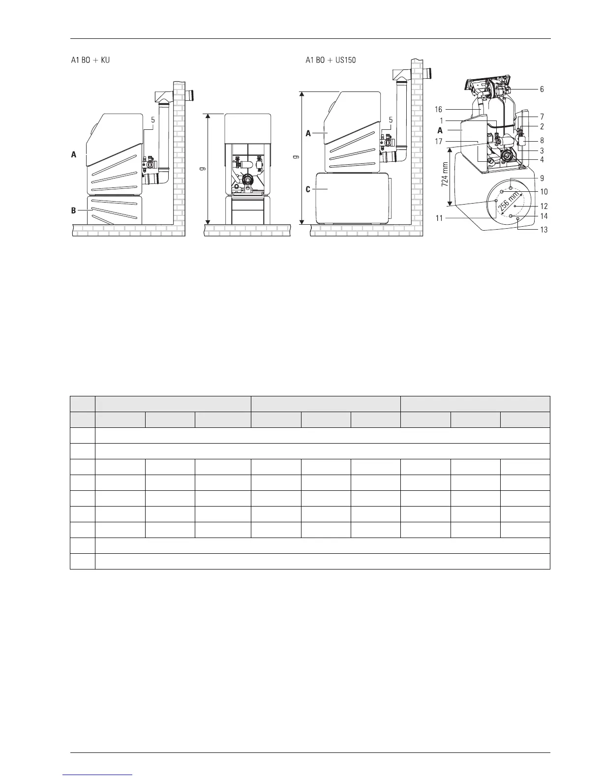
Tab. 3-1 Installation dimensions for oil condensing boiler A1 B0 in mm
Fig. 3-3 Dimensions and connection dimensions of the different set-ups
1 Boiler return flow
2 Boiler flow
3 KFE cock connection on the unit filling
line connection on KFE cock
4 Flue gas/supply air connection
5 Connection expansion vessel
6 Burner
7 Safety valve
8 3-way diverter valve
9 Hot water
10 Circulation
G 1" IT (Box nut)
G 1¼" ET / G 1" IT
G ½" IT
G ½" ET
DN 80/125
G ½" IT
G ½" IT (Bleeding line G ¾" IT)
G 1" ET
G ¾" IT
G ¾" IT
11 Heat exchanger return flow
12 Sensor immersion sleeve
13 Heat exchanger flow
14 Cold water
15 Air/flue system (LAS) Connection piece
16 Air supply hose
17 Condensate drainage hose
A ROTEX A1 BO
B Boiler frame (KU)
C Sub-tank (US 150)
G ¾" ET
G ¾" ET
G ¾" IT
DN 80/120
DN 50
DN 40
A1 B0 15bio / A1 B0 20i A1 BO 27i A1 BO 35i
Dim. on the floor on US 150 on stand on the floor on US 150 on stand on the floor on US 150 on stand
a
U400
b 720
c
Y137 Y785 Y499 Y137 Y785 Y499 Y137 Y785 Y499
d 230
F
15
880
F
15
590
F
15
230
F
15
880
F
15
590
F
15
230
F
15
880
F
15
590
F
15
e 400
F
15
1040
F
15
790
F
15
460
F
15
1100
F
15
850
F
15
460
F
15
1100
F
15
850
F
15
f U1340 U1890 U1650 U1470 U2020 U1770 U1590 U2140 U1890
g 1100 1730 1480 1220 1850 1600 1340 1970 1720
h 625
i 300