5 x Control
38
FA ROTEX A1 B0 - 10/2007
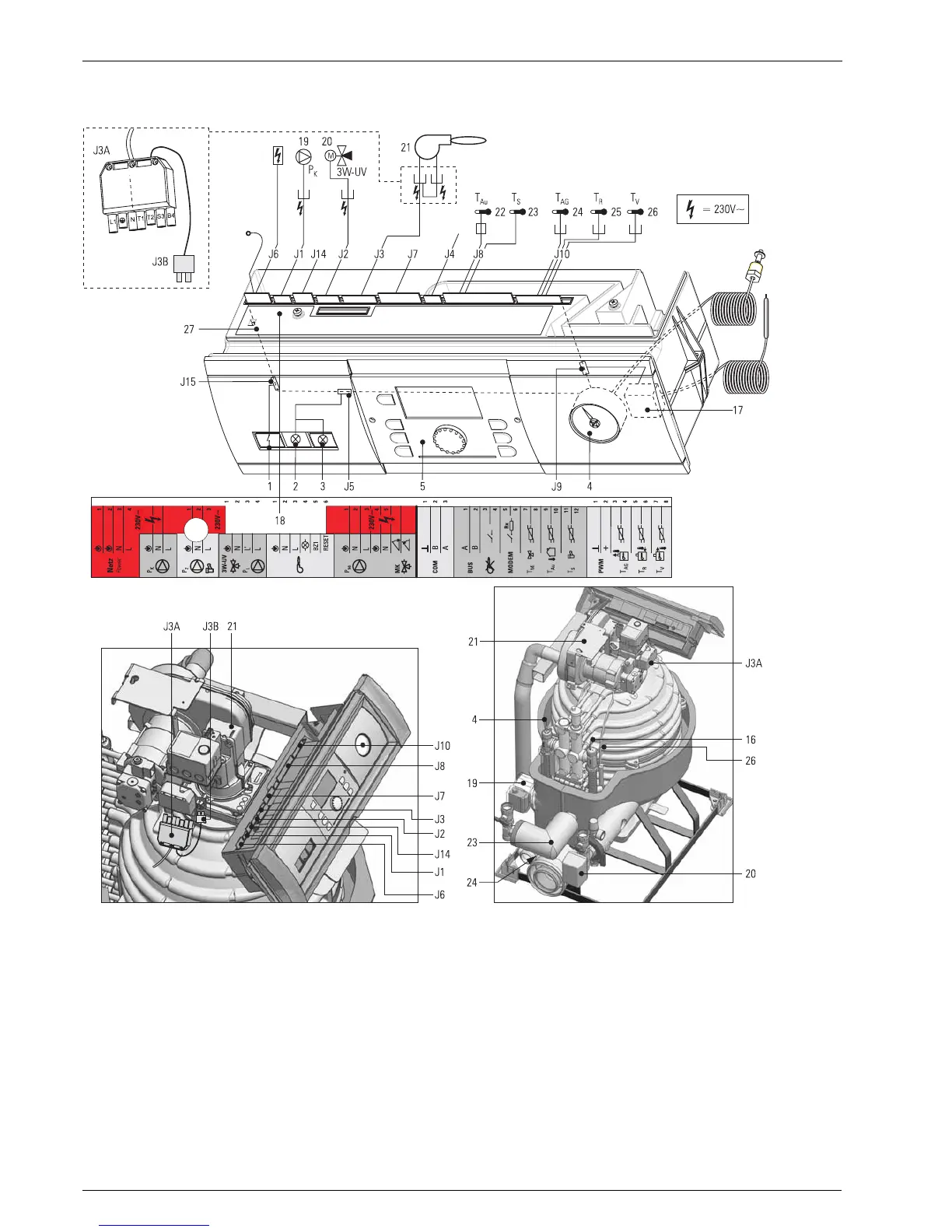
5.8 Wiring diagram
Fig. 5-18 Wiring diagram for oil condensing boiler A1 BO (shown with ROTEX THETA 23R Control)
1 Main switch
2 Burner malfunction indicator
3 STL indicator
4 Manometer
5 Controller: Central unit THETA 23R
17 safety temperature limiter (STL)
18 Stickers for connection diagram
19 Circulation pump for heating
20 3-way diverter valve
21 Oil burner
22 Outside temperature sensor
23 Storage tank temperature sensor
24 Flue gas temperature sensor
25 Return flow temperature sensor
26 Flow temperature sensor
27 Switchboard PCB
J1 3-pin circuit board connector with pump cable
J2 4-pin circuit board connector with valve cable
J3 6-pin circuit board connector with clamped
burner cable
J3A Standard connector oil burner (7-pin)
J3B 2-pin plug for remote burner unlocking
J4 Communication connection internal (not loaded)
J5 4-pin circuit board connector with malfunction
indicator cable
J6 4-pin circuit board connector with clamped mains
cable and earthing slots
J7 7-pin circuit board connector for clamping a mixer
motor and a mixer circulation pump
J8 12-pin circuit board connector for clamping
sensors, BUS- and control lines (storage
temperature sensor and cable for external sensor
are clamped)
J9 5-pin circuit board connector with STL cable
J10 8-pin circuit board connector with flue gas, flow
and return flow sensor cable
J14 3-pin circuit board connector for clamping
a circulation pump
J15 4-pin circuit board connector with switch cable