3x Set-up and Installation
18
FA ROTEX A1 BO - 10/2007
3.5.2 Connecting the flue gas pipe to the oil condensing boiler
Requirements:
– The flue system fulfils the requirements described in section3.5.1.
– The flue system fulfils any other required national or regional safety requirements.
– The oil condensing boiler is correctly connected.
Connection:
• Connect the oil condensing boiler to the flue system in the installation room (for connection dimensions refer to fig 3-6 and
tab. 3-4).
• Place the nameplate of the flue gas pipe in the installation room.
Tab. 3-4 Connection dimensions for the LAS connection of the oil condensing boiler
14 478 (ref. to chapter 3.5.1):
We recommend using the associated ROTEX flue gas kits (see fig 3-5). They satisfy all requirements and are
also fitted with special acid-proof seals.
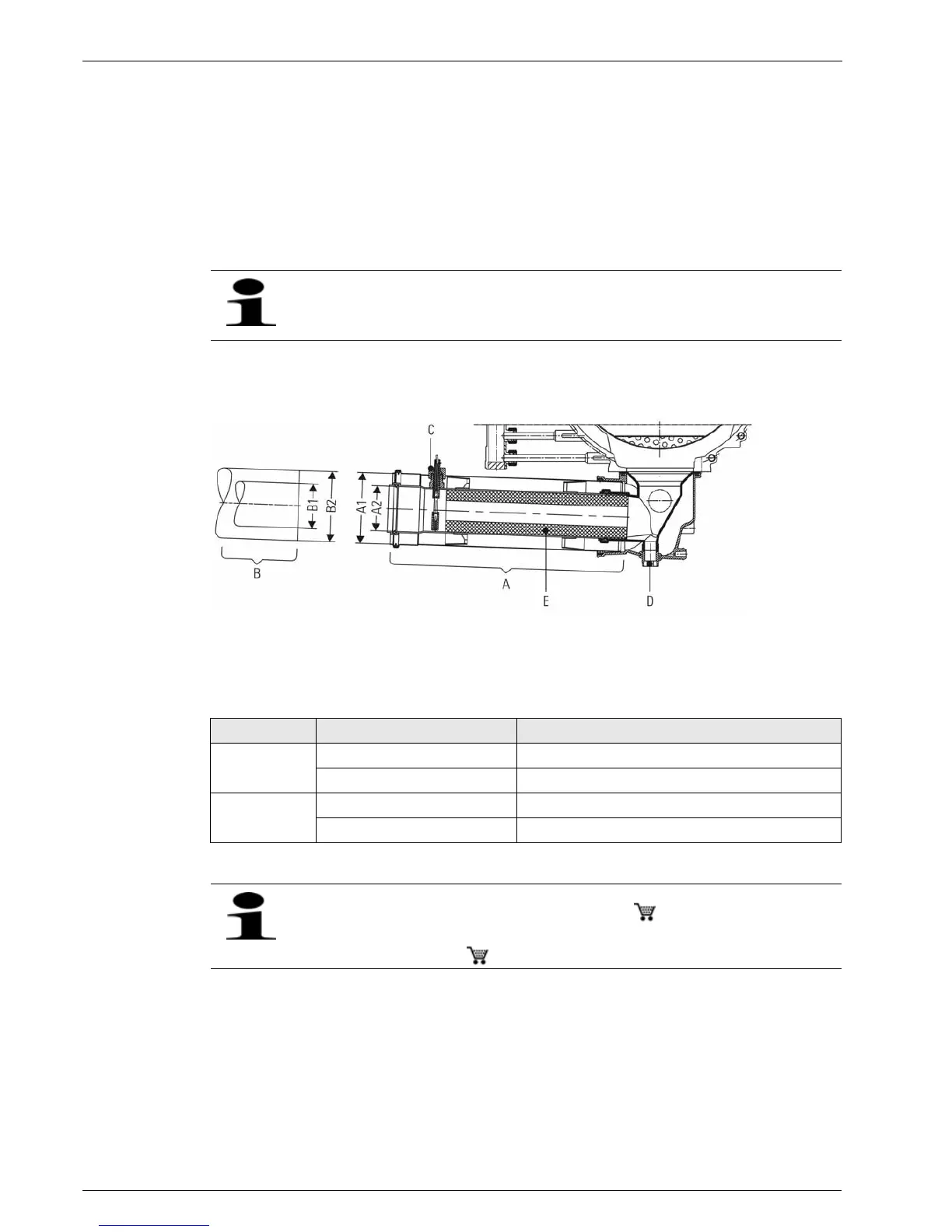
Fig. 3-6 Connection dimensions LAS Twin skin flue of oil condensing boiler of series A1 BO
A Boiler connection
B Flue gas connection
C Flue gas temperature sensor
D Connection for condensate drain
E Flue gas noise damper (not in A1 BO 35i)
Connection side Connection Connection dimension in mm
A Boiler side A1 Flue gas DN 80 Collar Inner diameter = 80.4 +0.8
A2 Supply air DN 125 Collar Inner diameter = 127.0 –0.5
B Flue gas side B1 Flue gas DN 80 Outer diameter = 80.0 +0.3
B2 Supply air DN 125 Outer diameter = 126.0 ±0.3
In some cases, the resonance in the flue system can amplify the noise at the mouth of the flue gas pipe.
The noise level can be effectively reduced by using a noise damper ( 15 45 78).
Air suction noises are generated during ambient air-dependent operation. The noise level can be effectively
reduced by using a noise damper ( 15 45 77).