6 x Oil burner
44
FA ROTEX A1 BO - 10/2007
Tools required: Flue gas analysis unit for determining the emission values for NO
x
and CO in the flue gas.
• Connect the flue gas analysis unit.
• Adjust the position of the recirculation gap with adjusting screw (for setting, see tab.6-1).
• Shut down and wait for about 5 minutes.
• Restart the burner.
Î Burner does not start or is late: Reduce the width of the recirculation gap (lower scale value).
• Check emission values for NO
x
and CO (observe country-specific regulations).
6.3.6 Check and set electrode distance and the distance between oil nozzles and air nozzles
Checking and setting electrodes distance
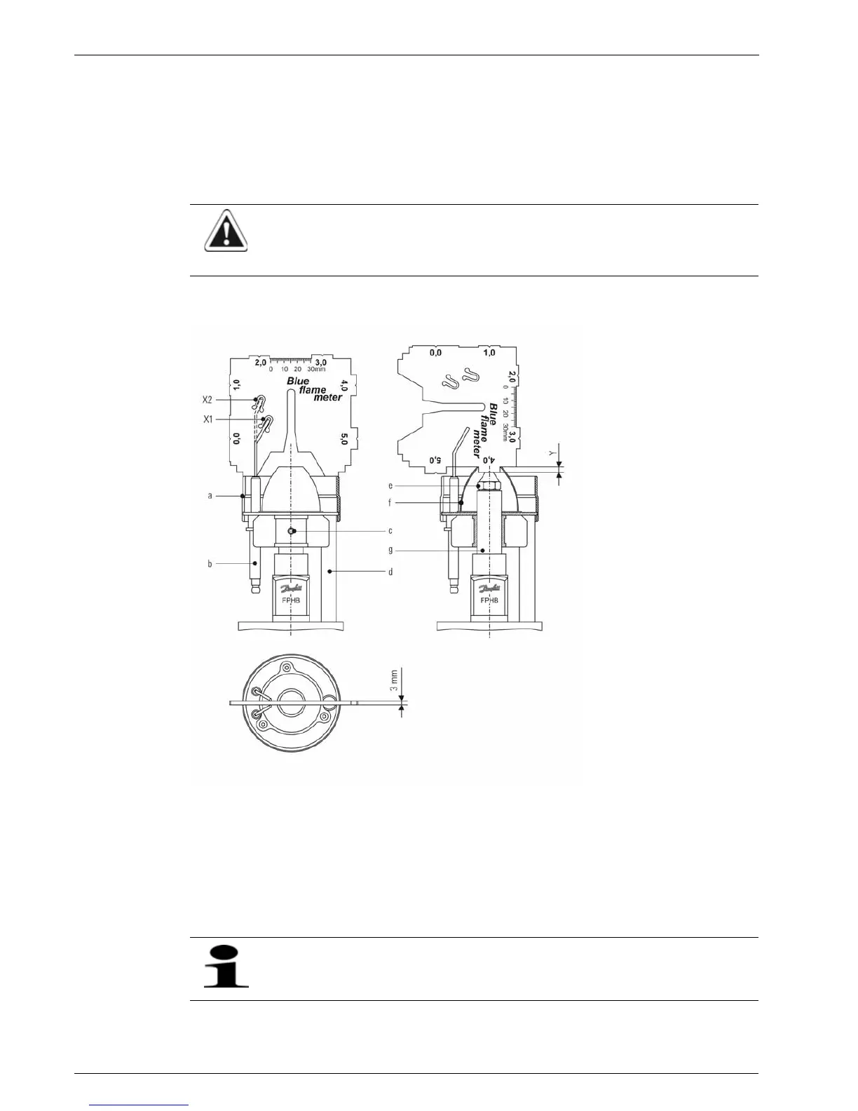
Tools required: Feeler gauge "Blue Flame Meter" (fixed on the holder for the service position);
• Put burner in service position (see chapter 6.4).
• Check electrode distance and position with feeler gauge "Blue Flame Meter".
• If necessary, readjust electrodes by bending them.
CAUTION!
If the recirculation gap is too small or closed, it will cause a sudden temperature rise in the mixing device and
can damage the mixing device.
a Mixing unit
b Ignition electrodes
c Fixing screw
d Light tube
e Oil nozzle
f Air nozzle
g Nozzle rod
X1 Electrode position BL 15, BL 20
and BL 27
X2 Electrode position BL 35
Y Distance oil nozzle – air nozzle
Fig. 6-8 Check electrodes setting and distance oil nozzles - air nozzles
If the ignition electrodes are worn out, they must be replaced.
Notes on replacing the ignition electrodes are given in section 8.2.8.