7 x Hydraulic connection
48
FA ROTEX A1 BO - 10/2007
7 Hydraulic connection
7.1 Integrated connection group
7.1.1 Design and function
The integrated connection group is a compact unit for connecting a heating circuit and a hot water tank to the oil condensing
boiler ROTEX A1 BO.
The integrated circulation pump allows the required water to flow through the oil condensing boiler and the active circuit (hot
water storage tank or heating circuit).
The 3-way diverter valve switches between the heating circuit and the hot water storage tank as required by the boiler control.
7.1.2 Releasing / restoring electrical connections
The integrated connection group is wired into the boiler control panel. The integrated heating circuit pump and the 3-way diverter
valve on the unit are connected with plugs.
• When changing the boiler control panel or the pump, unplug the pump cable from the terminal box on the pump.
• Plug the 6-pin plug into the valve drive socket to connect the 3-way diverter valve (shape-coded).
Note the following for emergency operation if the valve drive is faulty:
• Press the unlocking button (fig, 7-1, pos. 2.2) and rotate the motor head of the valve drive (fig, 7-1, pos. 2.1) 1/4 turn to the
left and remove.
Î The 3-way diverter valve is set to the "Heating" position.
Note the following for the temporary manual parallel operation of the heating circuit and the hot water storage tank:
• Pull the 6-pin plug out of the valve drive.
• Move diverter valve to centre position with hand lever (fig, 7-1, pos. 2.3) (only possible if the valve drive is already in
"Heating" position).
If the pumping capacity of the integrated circulation pump is not enough to supply of the heat distribution
network (see fig, 11-2 to fig, 11-5), an additional pump can be installed in the heat distribution network.
The additional pump must be uncoupled from the boiler circuit (e.g. through a hydraulic switch point).
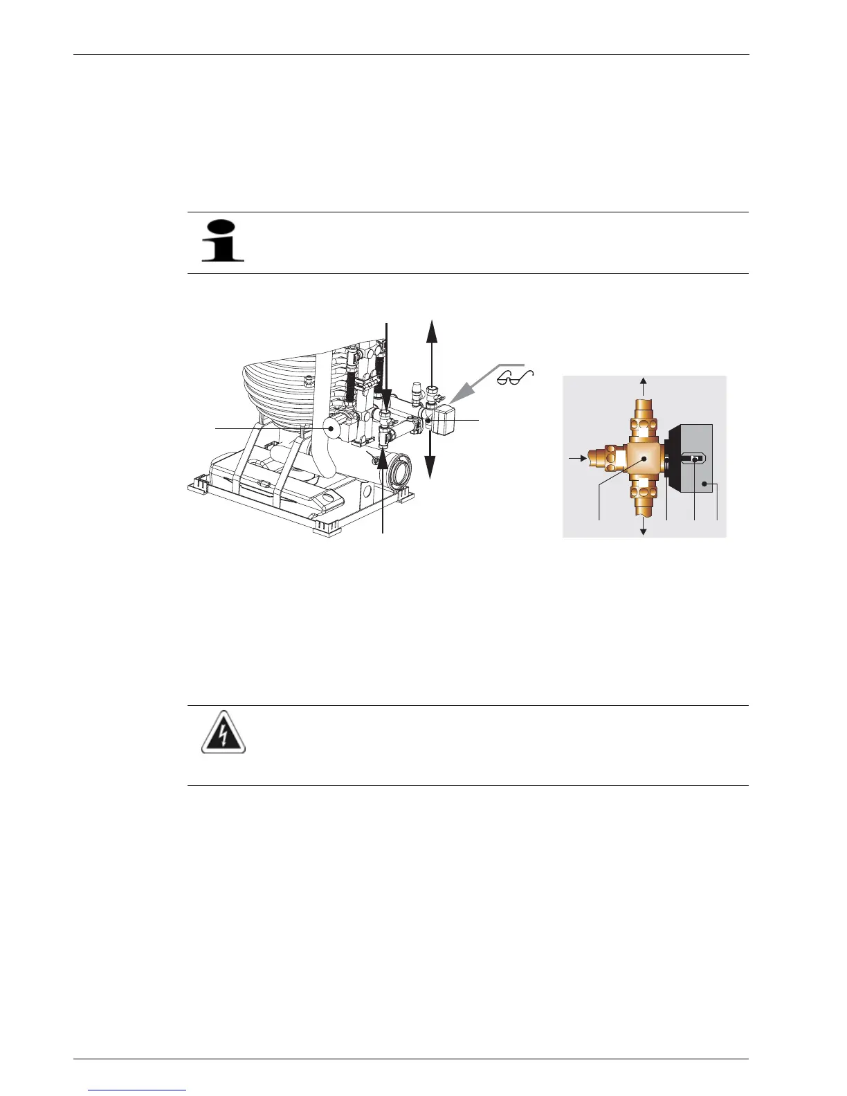
Fig.7-1 Integrated connection group
1 Circulation pump
2 3-way diverter valve
2.1 Valve drive
2.2 Unlocking button of the drive lock
2.3 hand lever (shown in filling position)
3 Boiler flow (Connection AB)
4 Heating flow (connection B)
5 Storage tank charging flow (connection A)
a Heating flow 1" IT
b Heating return flow 1" IT
c Storage flow 1" ET
d Storage tank return flow 1" ET
WARNING!
Live parts can cause an electric shock on contact and cause life-threatening burns and injuries.
• Disconnect from the power supply before beginning work on the integrated connection group (remove
fuse, switch off main switch) and secure against unintentional restart.
b
c
d
1
2
a
X
B
A
AB
4
3
5
2.2
2.1
2.3
2
X