3 x Set-up and Installation
17
FA ROTEX A1 BO - 10/2007
Installation position and piping height:
– The maximum permitted flue gas counterpressure is 200 Pa. The pressure loss in the supply line must not exceed 50 Pa.
– Angle of entry of the flue gas pipe into the chimney or installation shaft: approx. 3°.
– Slope for horizontal parts of the flue gas pipe: approx. 3°. Counter-slopes are not allowed at any point in the flue gas pipe.
– If the flue gas pipe needs more than 3 deflections > 45°, then the maximum permitted height for the flue gas pipe is reduced
by at least 1 m per deflection (flue gas calculations may be needed).
– If the horizontal connecting piece is extended, the maximum permitted height of the flue gas pipe is reduced by exactly that
length.
–The minimum height of the flue gas pipe must be 2m in order to avoid malfunction when starting or while operating the
burner.
Tab. 3-3 Maximum permitted height of the flue gas pipe in m (when operating in the nominal output range)
1) Shaft cross section for DN 80: 135 mm x 135 mm; Shaft cross section for DN 110: 160 mm x 160 mm
Any restriction on the output range may require a recalculation of the maximum permitted height for the flue gas pipe. The
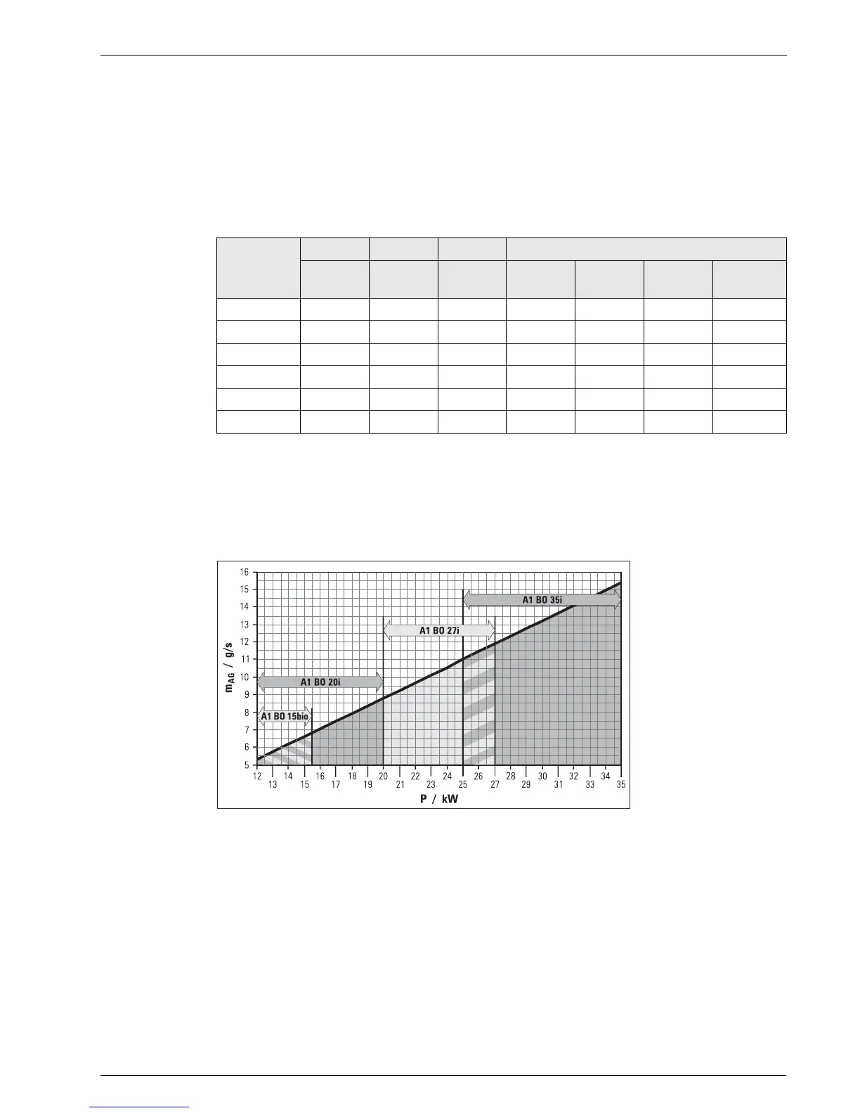
characteristics for the flue gas calculation can be obtained from fig 3-5 and chapter11 "Technical data“.
The flue gas mass flow of the systems depends on the burner output set.
Set-up version
(ref. fig 3-4)
A1 BO 15bio A1 BO 20i A1 BO 27i A1 BO 35i
DN 80 DN 80 DN 80 30 kW
DN 80
33 kW
DN 80
35 kW
DN 80
35 kW
DN 110
1
1)
16 16 16 20 16 8 24
2
1)
21 21 21 21 21 21 30
3
1)
17 17 17 21 21 17 30
4 16161620202028
5 17171711111123
6 17171711111123
Fig. 3-5 Flue gas mass flow in relation to the burner output
m
ET
Flue gas mass flow P Burner output