8 x Inspection and maintenance
57
FA ROTEX A1 BO - 10/2007
• Disconnect the oil condensing boiler from the power supply (fuse, main switch off) and secure against unintentional restart.
• Remove four Allan screws M10 (see fig. 8-12).
• Tilt the combustion chamber upwards (see fig. 8-13). An air pressure spring keeps the upper half of the combustion chamber
open.
• Only in A1 BO 27i and A1 BO 35i: Remove cylindrical combustion chamber ring.
• Remove combustion chamber insert with the help of the combustion chamber key (fig. 8-14 and fig.8-15).
Cleaning the combustion chamber
Depending on the heating oil quality and the operating temperatures, deposits and contamination of varying intensity are formed
in the A1 BO.
Requirement:
The gap between the boiler half shell in the joint area is covered to prevent residues from the upper boiler half shell from falling
into the gap.
Special tool: Cleaning brush, cleaning scraper (included in scope of supply).
Remove dry residue (mostly in the upper boiler half cup):
• Loosen the dirt and soot on the combustion chamber ribs by using the cleaning brush and cleaning scraper.
• Suction off the loosened dirt and soot by using a vacuum cleaner.
In the transition area between dry and moist combustion chamber areas (mostly in the lower boiler half cup) there is hard residue
that can be removed only with wet cleaning. For this:
• Loosen dirt and rust under running water spray (fig. 8-16) with cleaning brushes and scrapers.
• Rinse off loosened dirt with clean water into the drain.
Always remove any existing residue with high pressure cleaner. For this purpose:
• Close combustion chamber without combustion chamber insert.
• Unscrew burner incl. burner flange (see chapter 6.4).
• Clean combustion chamber through burner flange opening with high pressure cleaner (fig. 8-17).
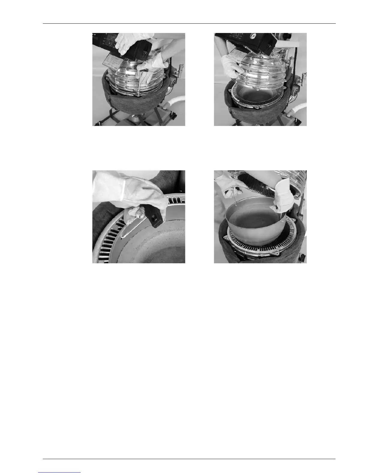
Fig. 8-12 Opening the combustion chamber Fig. 8-13 Fold the combustion chamber upwards
Fig. 8-14 Attach combustion chamber key
(shown A1 BO 20i)
Fig. 8-15 Lift out the bottom combustion chamber insert
(shown A1 BG 20i)