4 x Start-up and taking out of service
25
FA ROTEX Solaris RPS3 P2 - 06/2012
4.1.2 Filling storage tank circuit (system without FlowSensor)
1. Filling the hot water storage tank:
• Fill the heat exchanger for domestic water.
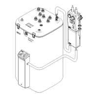
• Fill buffer storage volume via the filling and draining cock (accessory 16 41 17) on the Solaris RPS3 P2 control and
pump unit until the water starts flowing out of the safety overflow.
• Close the filling and draining cock (accessory 16 41 17).
2. Switch on Solaris RPS3 P2 control and pump unit (initialisation phase begins).
3. After the initialisation phase (temperature display), vent the system by pressing the two arrow keys simultaneously (start
manual operation).
Î The pump now operates at full power and the system is at the maximum possible operating pressure. The storage tank
circuit fills, the air is vented through the feed line into the air space of the hot water storage tank.
A bypass in the FlowGuard regulating valve ensures that the system is vented automatically, even if the valve is fully
closed.
4. Close regulating valve completely. The system is now under the maximum possible operating pressure.
5. Check the entire system for leaky joints (in the building and on the roof). Any leaks must be eliminated properly.
6. Adjust flow depending on the number of solar panels. For reference values for the setting see tab. 4-2.
Table 4-2 Setting the flow at the FlowGuard (FLG)
7. Switch off Solaris RPS3 P2 control and pump unit.
8. Check the filling level in the hot water storage tank.
9. Only if the water level in the hot water storage tank is not close to the fill level:
• Switch on Solaris RPS3 P2 control and pump unit again (initialisation phase begins).
• When the initialising phase is finished (temperature display), you can start the manual operating mode by simultaneously
pressing both arrow keys.
• Measure the time until the inflow is heated at the plate heat exchanger.
• Set the measured time plus 5 s in the parameter "Time PsE" (see chapter 5.3.6).
10. Switch Solaris RPS3 P2 control and pump unit to Automatic mode by pressing both arrow keys down at the same time or
by performing another switch on/switch off. The system is now ready for operation.
11. Complete the thermal insulation at the connecting points.
12. Instruct the user, fill out the acceptance report, and send it to the address indicated on the rear cover of this manual.
The flow of the solar panel circuit can be checked at the flow display of the ROTEX RDS1 pressure station
(settings see tab. 4-2).
If a heat meter is installed in the system, the flow can be set based on the heat meter reading (settings
see tab. 4-2).
Number of
collectors
Nominal flow
in l/min
Desired flow in l/hour
Solar panel circuit Storage tank circuit Solar panel circuit Storage tank circuit
2 3.6 to 4.8 3.0 to 4.0 220 to 290 180 to 240
3 5.4 to 7.2 4.5 to 6.0 330 to 435 270 to 360
4 7.2 to 9.6 6.0 to 8.0 435 to 580 360 to 480
5 9 to 12 7.5 to 10.0 540 to 720 450 to 600
The pumps are only switched on if the temperature of the solar panels is higher than the minimum value coupled
to the minimum temperature of the storage tank (see chapter 5.2.9) and lower than the specified approved
maximum temperature.
If there is a longer period between step 5 and 7, the temperature of the solar panels may be outside the
approved range. If T
K
> T
K
zul it is not necessary to switch to manual operation.
 Loading...