5 x Operation
33
FA ROTEX Solaris RPS3 P2 - 06/2012
5.3 Setting and menu operation
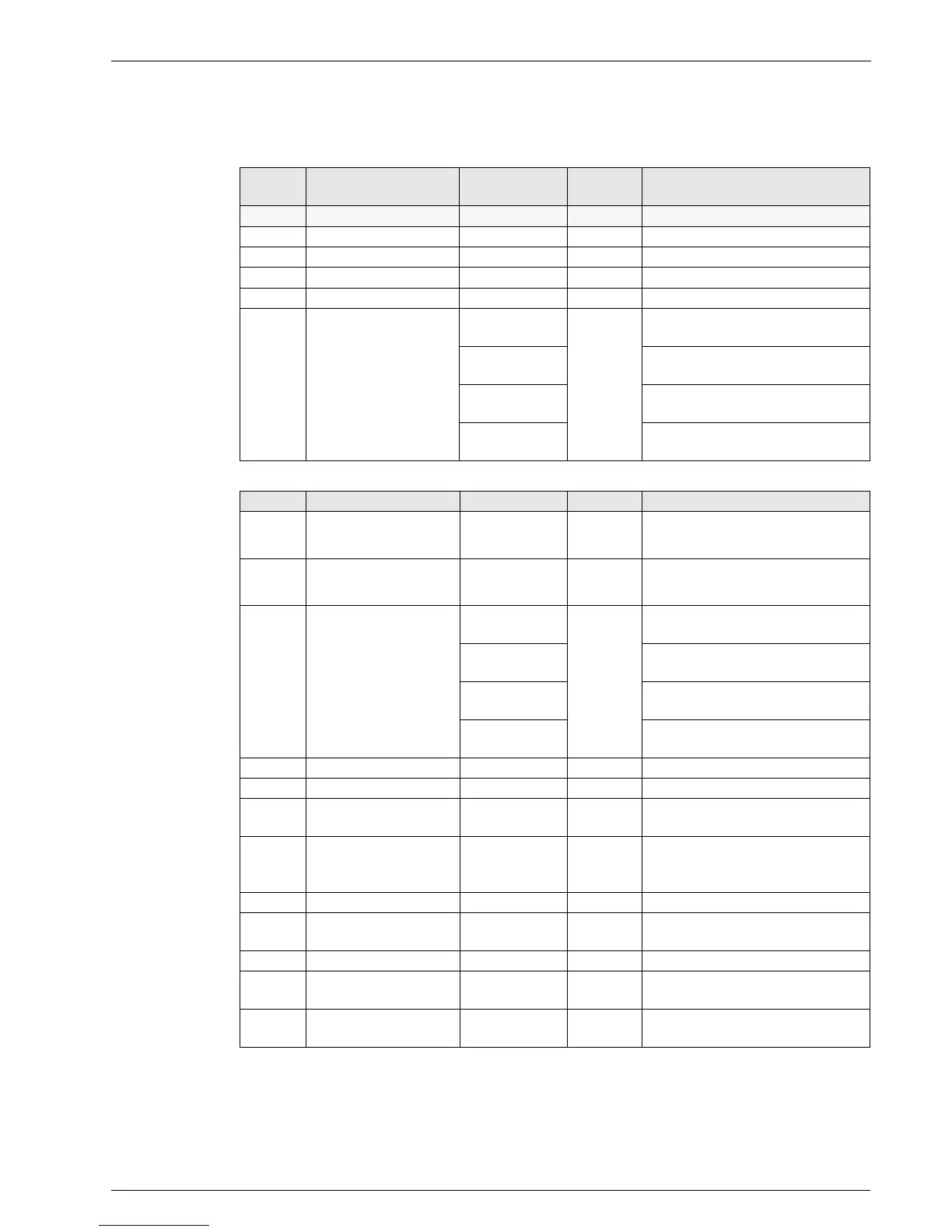
Table 5-2 shows an overview of the available measuring points and the associated display formats. Table 5-3 summarises the
views of the calculated parameters.
Table 5-2 Overview of measuring points
Table 5-3 Maximum values and calculated values
Measuring
point
Name Measuring range Resolution Sensor
Display
T
K
Solar panel temperature -30 to 250 °C 1 K PT 1000 temperature sensor
T
R
Return flow temperature 0 to 100 °C 1 K PTC temperature sensor
T
S
Storage tank temperature 0 to 100 °C 1 K PTC temperature sensor
T
V
Flow temperature 0 to 100 °C 1 K FlowSensor with voltage output 0.5 to 3.5 V
VFlow
0.0 to 12.0 l/min
0.1 l/min
FlowSensor 12 with voltage output
0.5 to 3.5 V
0.0 to 20.0 l/min
FlowSensor 20 with voltage output
0.5 to 3.5 V
0.0 to 40.0 l/min
FlowSensor 40 with voltage output
0.5 to 3.5 V
0.0 to 100.0 l/min
FlowSensor 100 with voltage output
0.5 to 3.5 V
Parameter Name Value range Resolution Remark
TK max
Maximum measured solar
panel temperature
-30 to 250 °C 1 K
none
TK min
Minimum measured solar panel
temperature
-30 to 250 °C 1 K
none
V max Maximum flow
0.0 to 12.0 l/min
0.1 l/min
Maximum flow that was reached during filling
with FlowSensor 12
0.0 to 20.0 l/min
Maximum flow that was reached during filling
with FlowSensor 20
0.0 to 40.0 l/min
Maximum flow that was reached during filling
with FlowSensor 40
0.0 to 100.0 l/min
Maximum flow that was reached during filling
with FlowSensor 100
PS Peak output 0.0 to 99.9 kW 0.1 kW Maximum value from 5 min output average
HP (15h) Daily peak output 0.0 to 99.9 kW 0.1 kW Maximum value of peak output in the last 15 h
W (15h) Daily heat yield 0.0 to 999.9 kW 0.1 kWh
Heat yield from instantaneous output in the
last 15 h
W Total heat yield
0.0 to 9999.9 kW
or 10.000 to
99.999 kW
0.1 kWh
0.0001 MWh
Total solar heat yield calculated from
instantaneous output
P Instantaneous output 0.0 to 99.9 kW 0.1 kW Average value of the last minute
DT Nominal spread 1 to 15 K 1 K
Nominal temperature difference T
V
–T
R
at
modulation operation (calculated)
P1 Current output stage P1 0 to 100 % 1 % none
Stage min
Lowest released output
stage P1
0 to 10;
0 to 100 %
1; 1 %
Only available with technician access
(see image 5-9)
Stage on
Runtime of tank circulation
pump P1
0 to 99999h 1 h
Only available with technician access
(see image 5-9)
 Loading...