6 x Faults and malfunctions
42
FA ROTEX Solaris RPS3 P2 - 06/2012
6 Faults and malfunctions
6.1 Display of events
Using the menu path: "Selection 2/2" -> "System" -> "Event memory" and after input of the technician password (see
chapter 5.3.4 and figure 5-9) the events occurring during operation can be displayed. The Solaris R3P control system has a simple
fault diagnosis system. The incidence memory stores nature and time of the event. The event is displayed in plain text and a code,
the time since the event occurred is shown in hours. Starting with the most recent event, you can leaf through the individual
events by means of the Info key. If the parameter "Delete" is in the menu path: "Selection 2/2" -> "System" -> "Event
memory" is set to "yes", all events are deleted. Deletion of individual events is not possible. For an overview of the event memory
see table 6-1.
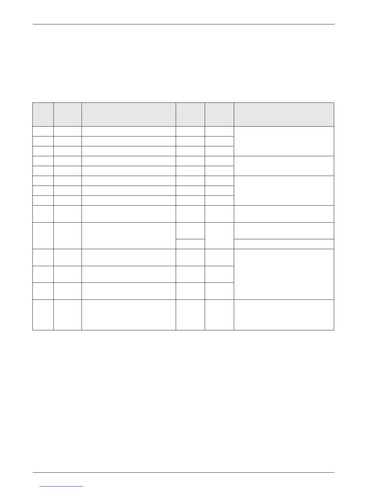
Tab. 6-1 Event memory
Sensor-specific fault signals
In the case of wire break and short-circuit in sensors or sensor cables the Solaris R3P control system responds as follows
(see table 6-2):
– The display shows a flashing identification letter for the malfunction in the status column and a message appears.
– The lamp associated with the sensor flashes.
– The Solaris R3P control system also automatically intervenes in the operation of the system.
All other sensor values remain accessible via the arrow keys.
Event
code
Plain text
display
Description Status
display
(flashing)
Lamp
(flashing)
Consequence
0 Collector Solar panel sensor: short-circuit or interruption K TK
Permanent switch-off of P1 and P21 Return flow Return flow sensor: short-circuit or interruption R TR
2 Storage tank Storage tank sensor short-circuit or interruption S TS
3 Flow FlowSensor: Short circuit or interruption D
Operation without FlowSensor
4 Inflow FlowSensor: Short circuit or interruption V
5 A/D Internal A/D converter fault G
Permanent switch-off of P1 and P26 Supply Internal device fault in supply voltage G
7 Reference Internal device fault in reference voltage G
8Reset
Overall reset was carried out
G Parameters to factory settings, restart the
equipment
12 Start flow
Minimum flow V1 (Figure 4.2) was not reached
in the start phase after "Time PsE" - description
Sec. 4
W
TV
Temporary shutdown of P1 and P2
(2 h / 3 start attempts)
F Permanent switch-off of P1 and P2
13 T
S
> Tmax Storage tank maximum temperature ("T
S
max")
exceeded - description Sec. 1
TS
Temporary switch-off of P1 and P2
14 T
R
> T
S
T
R
- T
S
> 10 K and T
R
> 40 °C - description
Sec. 2
TR
15 T
K
> T
K
zul Approved maximum solar panel temperature
("T
K
zul") exceeded - description Sec. 3
TK
16 Interrupt
Flow collapse during operating phase detected
(V < "S-Flow")
Temporary shutdown of P1 and P2 (at least for
stabilisation time), blockage of current and next
lower pump modulation stage, refill by P1 and P2
for "Time PsE" at next cut-in condition.
 Loading...