6 x Faults and malfunctions
44
FA ROTEX Solaris RPS3 P2 - 06/2012
The causes may include:
– a fault in the FlowSensors or
– vapour formation in the storage tank circuit or
– a leak in the storage tank circuit.
• If a leak is suspected, inspect the Solaris system, repair damage and then disable the block by switching the control system
off and on.
The fault signal "F" is shown in the left column of the Solaris R3P control system display. It follows three "W" fault signals with
2 h block time each. The system is now completely blocked and can only be restarted by user intervention. The causes may
include:
– a fault in the FlowSensors or
– vapour formation in the storage tank circuit or
– a leak in the storage tank circuit.
• If a leak is suspected, inspect the Solaris system, repair damage and then disable the block by switching the control system
off and on.
If circulation cannot be generation in the tank or solar panel circuit, it may be caused by the following faults:
1. Air brought in by draining the tank circuit is in the tank circulation pump.
• Check the pump for air. The automatic vent must always be in operation.
• Check the sealing cap and loosen it if necessary (do not remove).
2. Check the installation for leaks.
• Check the installation for leaks and rectify if necessary. Follow instructions in chapter 4 "Start-up and taking out of
service".
3. Increase the capacity of the pumps at the selector switch (1, 2, 3) for the individual pump.
If there is nothing showing on the display, and the main switch in the illuminated "On" position:
• Replace Solaris R3P control system (electronic fault).
If the main switch is not illuminated in the "On" position, there is no power supply to the control unit.
• Check the plug connection of the mains plug and the domestic power supply (fuse, switch).
If steam comes out of the hot water storage tank continuously under sunlight, the flow in the storage tank circuit is too low.
• In this case check the system settings and the hydraulics of both circuits.
Special instructions for electrical sensors
• Evaluate display in the Solaris R3P control system display.
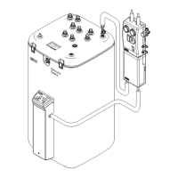
• Detach housing on the Solaris RPS3 P2 control and pump unit and remove the relevant sensor, unclamp where necessary.
• Examine the contact positions of the affected sensors, and measure the resistance (or the DC voltage for flow temperature
and flow rate sensors) on the sensor end.
When the fault has been rectified, the system automatically resumes normal operation and is in the operating mode.
The resistance or direct voltage values of the sensors are listed in image 8-2. Diagnosable internal faults of the control electronics
are shown in the display according to table 6-1 (status G). They also effect a safety switch-off of the pumps. Switching off and
on again after waiting for 2 min will either correct the fault or the Solaris R3P control system must be replaced.
Use only genuine ROTEX replacement parts.
 Loading...