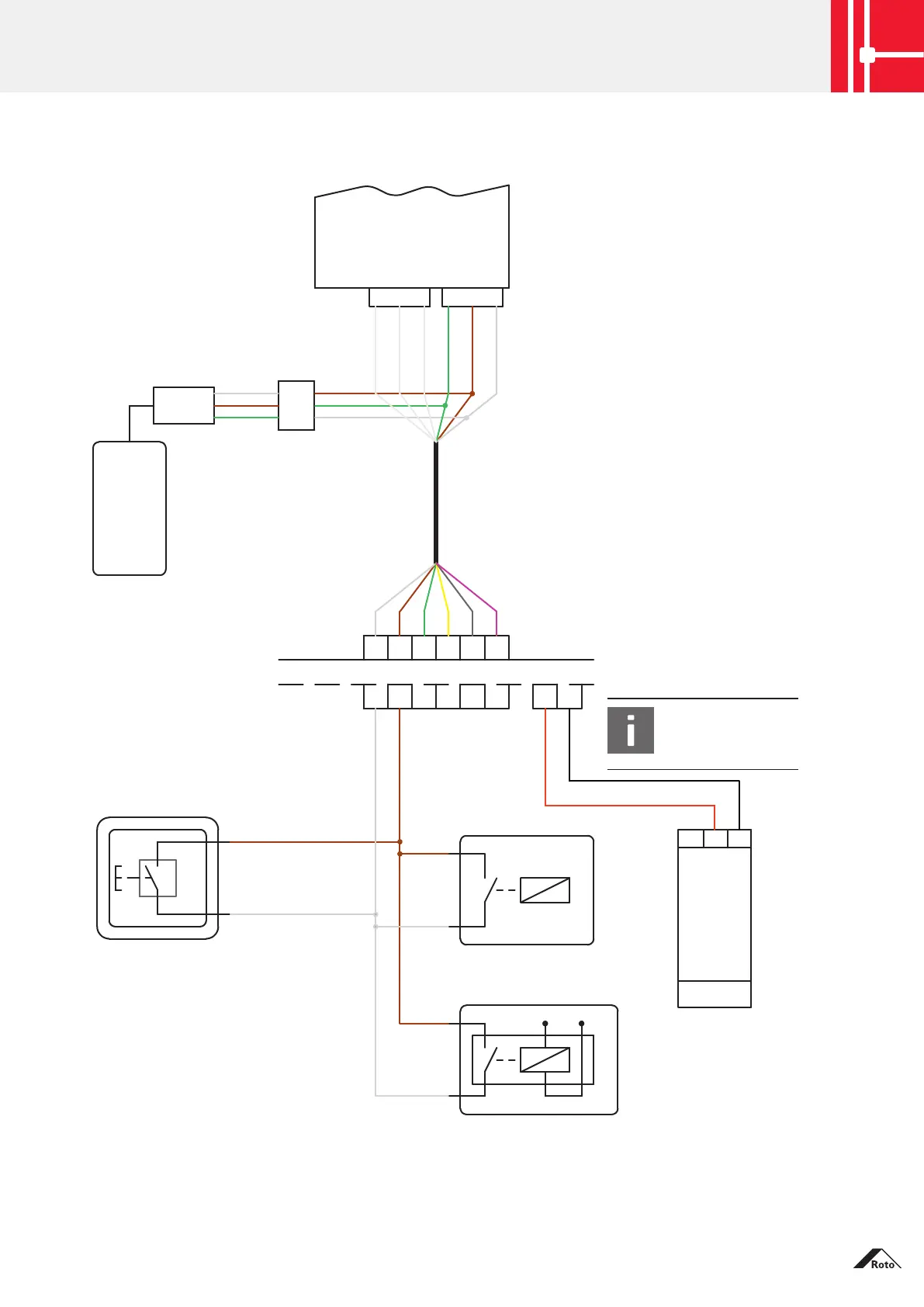
5.1 Eneo A / AF with Phone & Code, power supply unit in general
Eneo A / AF
GND
+24V
IN1
black green
unassigned
unassigned
unassigned
green
green
yellow
grey
pink
green
green
brown
brown
brown
brown
brown
brown
brown
brown
white
whitewhite
white
white
white
white
white
WhiteBlack Box
Access
control
system
Phone &
Code
Power
supply unit
IN:
100-230VAC
OUT:
24VDC
Video system
Push-button
Intercom
Inside
Outside
JST plug connection
EZ cable
3m
Sash side
Frame side
plug-in
cable junction
black
black
red
red
+24V
+24V
GND
GND
INFO
The 24V side
must not be wired.
230VAC
Cable, 3m
potential-free contact
potential-free contact
Signal (e.g. 12V)
Inside:
The “Unlock door” push-button
can be used as an option.
Phone & Code cable assignment
(between JST connector and Black Box)
white: +24V
brown: GND
green: control (OPEN)
Connector / cable assignment
white: IN1 / input 1 (OPEN)
brown: +24V
green: GND
yellow: IN2 / input 2
grey: unassigned
pink: unassigned
1
1 2
2 3
3 4
4 5
5
6
6
Connection diagram
Eneo A / AF with Phone & Code, power supply unit in general
Subject to change. Roto Safe - Cable junctions
IMO_502_EN_v2 · 05 / 2020 · 33