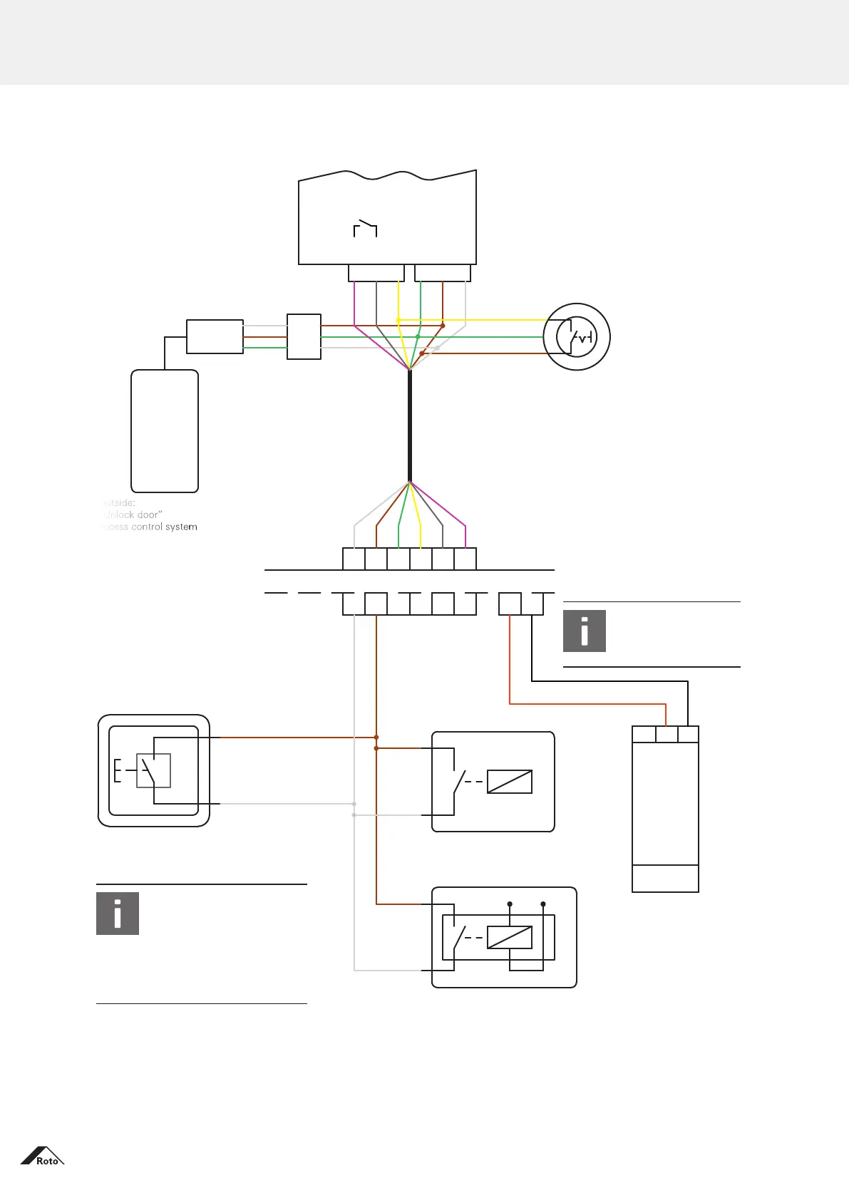
Outside
Outside:
“Unlock door”
access control system
JST plug connection
EZ cable,
3 m
Leaf side
Frame side
Plug-in
cable junction
Black
Black
Red
Red
+24 V
+24 V
GND
GND
230 V AC
Cable, 3 m
Potential-free contact
Potential-free contact
Signal (e.g. 12 V)
Inside:
“Unlock door” push-button,
optional for Eneo CC.
Phone & Code cable assignment
(between JST connector and Black Box)
White: +24 V
Brown: GND
Green: control (OPEN)
Connector / cable assignment
White: IN1 / input 1 (OPEN)
Brown: +24 V
Green: GND
Yellow: IN2 / input 2
Grey: K1a pot.-free contact
Pink: K1b pot.-free contact
Switch
“Day / night”
Inside:
can be used
as an option.
INFO
The 24 V side
must not be wired.
INFO!
The yellow wire must remain
unassigned; otherwise this will
bridge the switch on the leaf.
Terminals 5 and 6 are connected
to one another internally via
a relay and a 47 ohm resistor.
The maximum load of the contacts
is 24 V / 40 mA