LOCAL
OP LIM
LOCAL
OP LIM
EDIT
LOCAL
OP LIM
EDIT
LOCAL
OP LIM
4
5
OPTIONAL:
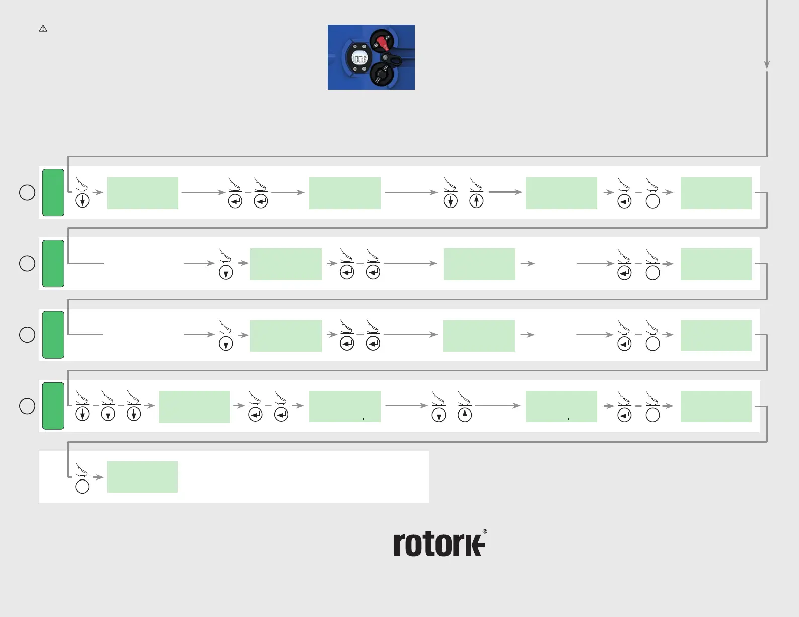
Calibrate 4-20 mA Signal
using external applied
signal LOW (Zero)
LOCAL
CMD 4
LOCAL
CMD 4
EDIT
LOCAL
CMD 4
Apply LOW
External
mA Signal
OPTIONAL:
Calibrate 4-20 mA Signal
using external applied
signal HIGH (Span)
LOCAL
CMD 20
LOCAL
CMD 20
EDIT
LOCAL
CMD 20
Apply HIGH
External
mA Signal
6
7
LOCAL
DBAND
LOCAL
DBAND
LOCAL
DB 1 00
%
EDIT
Example set at 1.00%
or
Adjust to desired % Deadband 0-10%
POS
I
T
LOCAL
Local Control is now set
Move knob to REMOTE for REMOTE CONTROL
X
SAVE
X
SAVE
X
SAVE
X
SAVE
LOCAL
DB 02
%
EDIT
Example set at 0.2%
Move Actuator to OPEN Position
or
CMA Range
Quick Start Guide
CML-1500 and CML-3000
Rotork plc
Brassmill Lane, Bath, UK
tel +44 (0)1225 733200
fax +44 (0)1225 333467
email mail@rotork.com
USA
Rotork Controls
tel +1 (414) 461 9200
fax +1 (414) 461 1024
email info@rotork.com
PUB094-022-00 Issue 08/18
These instructions enable the actuator to be
configured to suit the valve and must be carried
out before electrical start up. For complete
instructions refer to PUB094-019.
STEP 1
SELECT LOCAL
OPERATION
STEP 1
SET OUTPUT
TORQUE/TRUST
STEP 3
SET CLOSE LIMIT
OF TRAVEL
STEP 4
SET OPEN LIMIT
OF TRAVEL
STEP 5
CALIBRATE COMMAND
SIGNAL ZERO SETPOINT
STEP 6
CALIBRATE COMMAND
SIGNAL SPAN SETPOINT
STEP 2
SELECT ACTION AT END
OF TRAVEL ( LIMIT OR FORCE)
STEP 7
DEADBAND
STEP 1
SELECT LOCAL
OPERATION
STEP 1
SET OUTPUT
TORQUE/TRUST
STEP 3
SET CLOSE LIMIT
OF TRAVEL
STEP 4
SET OPEN LIMIT
OF TRAVEL
STEP 5
CALIBRATE COMMAND
SIGNAL ZERO SETPOINT
STEP 6
CALIBRATE COMMAND
SIGNAL SPAN SETPOINT
STEP 2
SELECT ACTION AT END
OF TRAVEL ( LIMIT OR FORCE)
STEP 7
DEADBAND
STEP 1
SELECT LOCAL
OPERATION
STEP 1
SET OUTPUT
TORQUE/TRUST
STEP 3
SET CLOSE LIMIT
OF TRAVEL
STEP 4
SET OPEN LIMIT
OF TRAVEL
STEP 5
CALIBRATE COMMAND
SIGNAL ZERO SETPOINT
STEP 6
CALIBRATE COMMAND
SIGNAL SPAN SETPOINT
STEP 2
SELECT ACTION AT END
OF TRAVEL ( LIMIT OR FORCE)
STEP 7
DEADBAND
STEP 1
SELECT LOCAL
OPERATION
STEP 1
SET OUTPUT
TORQUE/TRUST
STEP 3
SET CLOSE LIMIT
OF TRAVEL
STEP 4
SET OPEN LIMIT
OF TRAVEL
STEP 5
CALIBRATE COMMAND
SIGNAL ZERO SETPOINT
STEP 6
CALIBRATE COMMAND
SIGNAL SPAN SETPOINT
STEP 2
SELECT ACTION AT END
OF TRAVEL ( LIMIT OR FORCE)
STEP 7
CAUTION: Before commissioning
actuators fitted with the Reserve
Power Pack (RPP), please ensure
PUB094-019 is fully understood and
additional safety instructions are
followed where applicable.
Ensure the local control selector is set to
LOCAL during the commissioning process.
X
www.rotork.com
A full listing of our worldwide
sales and service network is
available on our website.
As part of a process of on-going product development, Rotork reserves the right to amend and change specifications without
prior notice. Published data may be subject to change. For the very latest version release, visit our website at www.rotork.com
The name Rotork is a registered trademark. Rotork recognises all registered trademarks.
Published and produced in the UK by Rotork. POWTG0818

 Loading...

