MODEL RB107
1. General
In Model RB107 control box, the regulator
and cut-out contacts are positioned, for ease of
access, above their respective armatures. It will
be noticed that some of the internal electrical
joints are resistance brazed.
2. Setting Data
(a) Cut-out
Cut-in voltage .................. 6.3-6.7 volts
Drop-off voltage ....... .. .... 4.8-5.3 volts
(b) Regulator
Setting on open circuit relative to ambient
temperature :
10° C. (50° F.) ............. ... ...... ... ... 7.7-8.1 volts
20° C. (68° F.) ............. ... ...... ... ... 7.6-8.0 volts
30° C. (86° F.) ............. ... ...... ... ... 7.5-7.9 volts
40° C (104° F.) ………… ……… 7.4-7.8 volts
3. Servicing
Before making any adjustment to the
regulator, ensure that the dynamo and battery
are in order. When a sound battery does not
keep in a charged condition, or if the dynamo
output does not fall when the battery is fully
charged, the following procedure should be
adopted :
(a) Checking the wiring between battery
and regulator
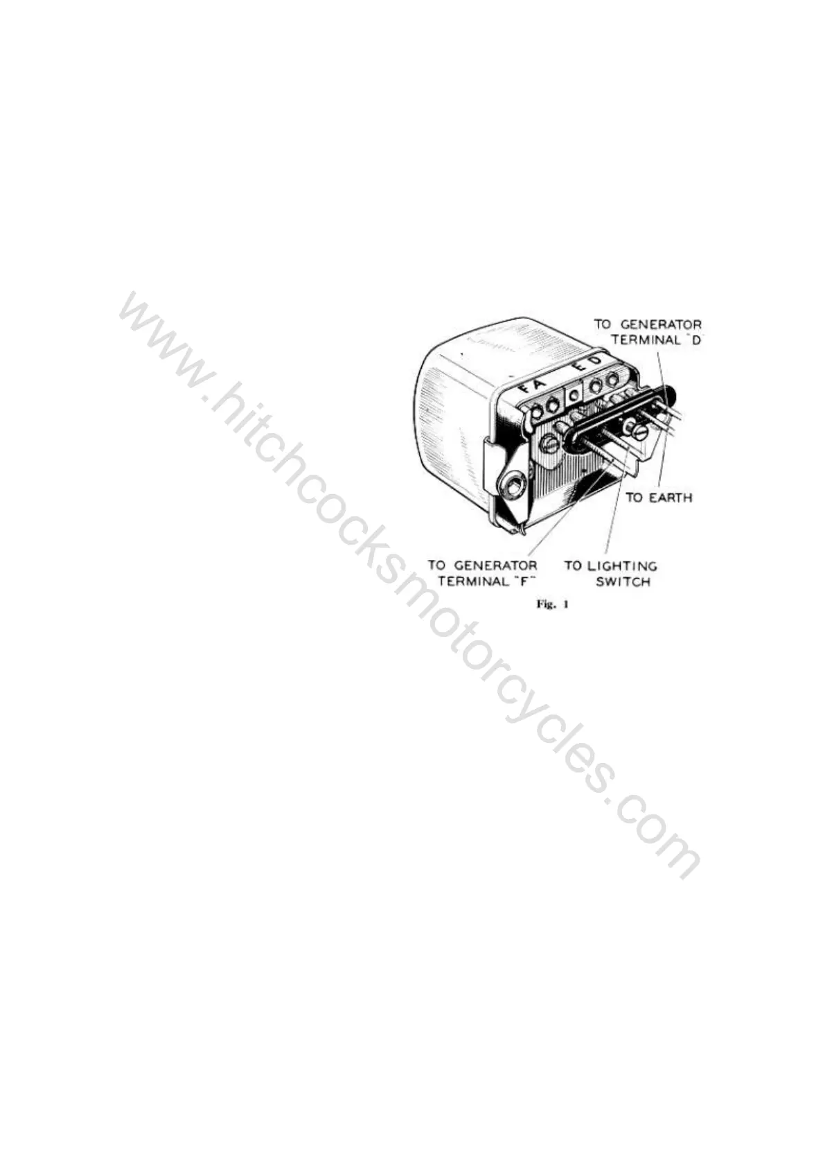
Remove the control box from its mountings
and withdraw the cable from terminal "A" (see
Fig. 1) and connect it to the negative terminal of
a voltmeter.
Connect the positive terminal of the
voltmeter to an earthing point on the machine. If
a voltmeter reading is given, the circuit from the
battery to terminal "A" is in order.
If there is no voltmeter reading, examine the
wiring between the battery and the control box
for defective cables or loose connections.
Re-connect the cable to terminal "A."
Check that the dynamo terminal "D" is
connected to control box terminal "D"and that
the cable is in good condition. Similarly, check
the cable between terminals "F" at the dynamo
and control box.
(b) Checking the electrical setting of the
regulator
The regulator is carefully set during
manufacture and, in general, it should not be
necessary to make further adjustment. If,
however, the charging system is suspected it is
important that only a good quality moving coil
voltmeter (0-20 volts) is used to check the
system. The electrical setting of the regulator
can be checked without removing the cover from
the control box.
Withdraw the plug-in connectors a small
distance, so that a voltmeter connection can be
made to terminals "D" and "E."
Connect the negative lead of the voltmeter to
control box terminal "D" and the positive lead to
terminal "E."
Remove the negative terminal from the
battery. If coil ignition is fitted, run a temporary
connection from the negative terminal of the
battery to the "SW" terminal of the coil.
 Loading...