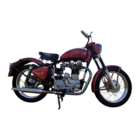
1. Description of Frame
The frames used on the above models are
basically identical, with swinging arm rear
suspension, but there are some small
differences in the lugs for engine attachment,
the method of attachment of the pivot point for
the swinging arm and in the width between the
brackets supporting the upper ends of the rear
suspension units. For part numbers of frames
see appropriate spares lists.
The frame is built throughout of cold drawn
weldless steel tubing with brazed or welded
joints, liners being fitted where necessary for
extra strength. All the main frame members
are made of chromemolybdenum alloy steel
tubing which retains its strength and resistance
to fatigue after brazing or welding.
The swinging arm unit which forms the
chain stays is provided with large diameter
phosphor bronze bushes and pivots on a stout
steel tube which is secured to the main frame
by a long bolt passing through the pivot lugs.
Hardened steel thrust washers are provided to
deal with side thrust. The torsional rigidity of
the swinging arm unit helps to maintain the
rear wheel upright in the frame and thus
relieves the wheel spindle of bending stresses
to which it is subject with other types of rear
suspension.
2. Steering Head Races
The steering head races, 34085, are the
same at the top and bottom of the head lug and
are the same for all models. They are easily
removed by knocking them out with a hammer
and drift and new races can be fitted either
under a press or by means of a hammer and a
wooden drift.
3. Removal of Rear Suspension Unit
The rear suspension units are readily
removed by undoing the top pivot pin nut,
driving out the pivot pin, then hinging the
suspension unit back on the lower pivot pin,
removing the lower nut and pushing the
suspension unit off the pivot pin welded to the
fork end.
4. Servicing Rear Suspension units
(a) Proprietary Units. The proprietary units
fitted to most 1954 and all 1955 models are
sealed and servicing of the internal mechanism
can be carried out only by the manufacturers.
The rubber bushes in the top and bottom
eyes can easily be renewed and the spring can
be removed by pushing down on the top spring
cover so as to release the split collar above it.
After removal of the split collar the top cover
and spring can be lifted off.
When reassembling, the spring should be
greased to prevent rust and squeaking if it
should come into contact with either of the
covers.
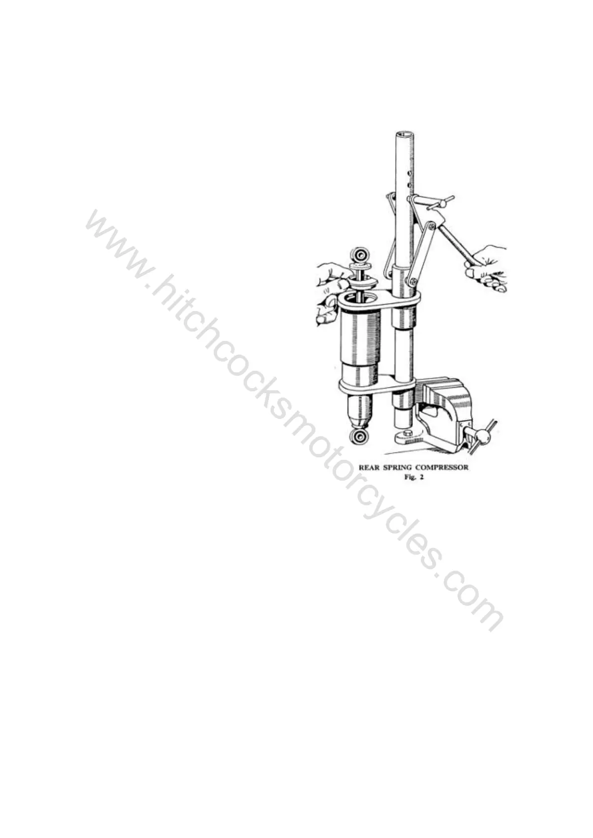
The standard solo springs have a rate of
100105lb. per inch and it is not difficult to
compress these by hand. Heavier springs
having a rate of 130lb. per inch are available
which may require the use of a spring
compressor, as shown in Fig. 2.
(b) Royal Enfield Units. Mark 1. Enfield
rear suspension units, Part Number 34276 or
36451, are shown in Fig. 3. Units having Part
No. 34276 are fitted with springs of .252 in.
diameter wire (Part No. 34284) having a
rating of approximately 200lb per inch (when
fitted on the scrolls).
 Loading...