Page 51
ROYAL ENFIELD 350cc and 500cc O.H.V. WORKSHOP MANUAL
removal of the main tube bush the bottom tube
bush, oil seal housing and oil seal can be
removed.In case of difficulty in removing the main
tube bush it is possible to withdraw the oil seal
housingafter loosening the crown clip bolt 39038,
removing the plug screw 38968 and unscrewing
the main tube from the fork-head by means of a
hexagon bar .500 in. across flats (Unbrako wrench
W. 11) or the special tool shown in Fig. 2.
4. Spring
Solo and Sidecar springs are available. The free
length of each is 20.1/2 ins. The spring should be
replaced if it has closed by more than 1 inch.
5. Reassembly of Parts
When refitting the oil seal, or fitting a new one,
great care must be exercised not to damage the
synthetic rubber lip which forms the actual seal. If
the seal has been removed from the upper end of
the main tube and is refitted from this end a
special nose piece (Fig. 3) must be fitted over the
end of the tube to prevent the thread from
damaging the oil seal.
The spring stud is a tight fit in the hole at the
lower end of the bottom tube. Once the stud has
been entered in the hole push the bottom tube
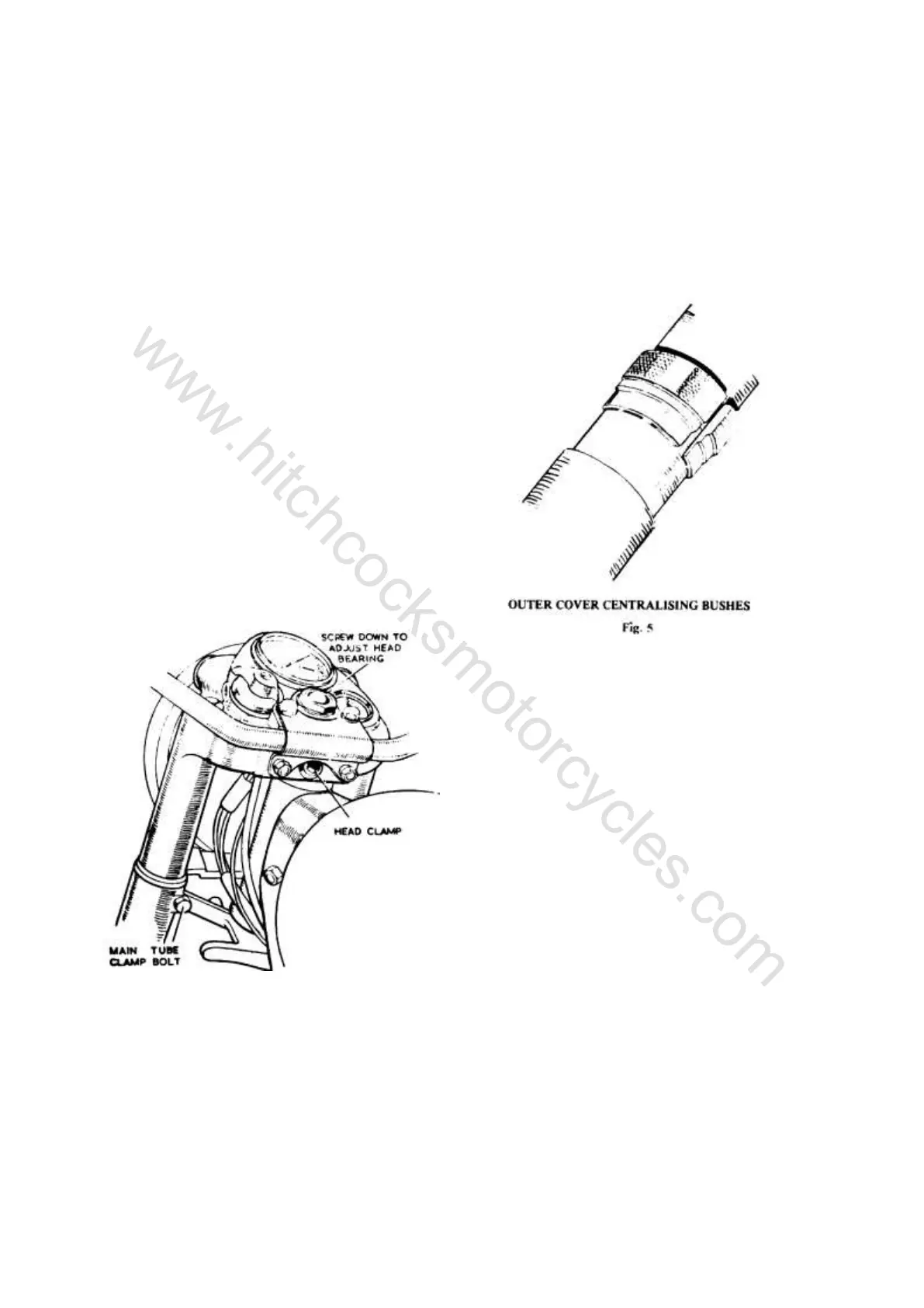
SHOWING THE POSITIONS OF THE CLAMP BOLTS
SECURING THE STEERING STEM AND FORK TUBES
Fig. 4
up sharply against the spring until two or three
threads on the stud project beneath the end of
the bottom tube. Now fit the nut and washer and
pull the stud into position by tightening the nut.
If necessary fit the nut first without the washer
until sufficient thread is projecting to enable the
washer to be fitted.
6. Steering Head Races
The steering head bearing consists of two
deep groove thrust races each containing
nineteen 1/4 in. diameter balls. The bearing is
adjusted by tightening the steering stem locknut
after loosening the ball head clip screw and both
the fork crown clamp bolts. The head should be
adjusted so that, when the front wheel is lifted
clear of the ground, a light tap on the handlebars
will cause the steering to swing to full lock in
either direction, while at the same time there
should be only the slightest trace of play in the
bearings. When testing for freedom of
movement the steering damper, if fitted, should
be disconnected by unscrewing the anchor plate
pin. Do not forget to tighten the ball head clip
screw and fork crown clamp bolts. Before
tightening the latter make sure that the cover
tubes are located centrally round the main tubes
so that the bottom tube does not rub inside the
cover tube. A pair of split bushes (Fig. 5) is
useful to ensure centralisation of the cover tubes.
7. Removal of Complete Fork
The fork complete with front wheel and
mudguard can be removed from the machine if
necessary by adopting the following procedure.
full of oil. Upward movement of the wheel
spindle forces oil from the lower chamber "A"
through the annular space between the spring
stud (38067) and the bore of the main tube valve
port (38138) into the damper chamber "B."
During this stroke the pressure on the underside
of the valve plate (38073) causes this to lift so
that oil can also pass from "A" to "B" through
the eight holes in the valve body. Since,
however, the diameter of chamber "B" is less
than that of chamber "A" there is not room in
"B" to receive all the oil which must be displaced
from "A" as the fork operates. The surplus oil
passes through the cross hole in the spring stud
and up the centre hole in the stud, spilling out
through the nut (38076) which secures the upper
end of the spring stud to the bronze guide at the
lower end of the fork spring.
On the rebound stroke the oil in the damper
chamber "B" is forced through the annular space
between the spring stud and the bore of the main
tube valve port. During this stroke pressure in
chamber "B" closes the two disc valves at the
upper and lower ends of the chamber so that the
only path through which the oil can escape is the
annular space between the spring stud and the
port. Damping on the rebound stroke is therefore
heavier than on the bump stroke. At the extreme
end of either bump or rebound stroke a small
taper portion on the spring stud enters the bore
of the valve port, thus restricting the annular
space and increasing the amount of damping. At
the extreme end of the bump stroke the larger
diameter taper on the oil control collar (38075)
enters the main counterbore of the valve port
thus forming a hydraulic cushion to prevent
metal to metal contact.
3. Dismantling the Fork to Replace Spring,
Oil Seal or Bearing Bushes
Place the machine on the centre stand,
disconnect the front brake control and remove the
front wheel and mudguard complete with stays.
Unscrew the bottom spring stud nut (38080)
which will allow oil to run out of the fork down
to the level of the cross-hole in the spring stud.
Now knock the spring stud upward into the fork
with a soft mallet, thus allowing the remainder
of the oil to escape. Pull the fork bottom tube
down as far as possible, thus exposing the oil
seal housing (38157). Unscrew this housing
either by means of a spanner on the flats with
which it is provided or by using the gland nut
handgrips (E.5417). The bottom tube can now
be withdrawn completely from the main tube,
leaving the bottom tube bush, oil seal housing
and oil seal in position on the main tube.
Now unscrew the main tube valve port using
"C" spanner (E5418). The spring stud and
spring can now be withdrawn from the lower
end of the main tube.
The steel main tube bush (38156) can now
be tapped off the lower end of the tube, if
necessary using the bottom tube bush for this
purpose. Before doing this, however, it is
advisable to mark the position of the bush with
a pencil line so as to ensure reassembling it in
the same position on the main tube. The reason
for this is that these steel bushes are finish
ground to size after fitting on to the tubes so as
to ensure concentricity to the main tube. After
www.hitchcocksmotorcycles.com
 Loading...