ECT Series User Manual
34
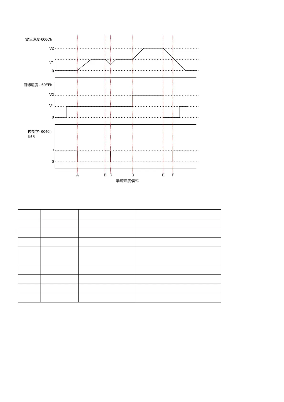
The above figure shows the corresponding relationship between the motor running status,
actual speed, target speed and control word.
Motor decelerates to stop
Before the motor stopped, it
accelerated to V1.
Motor accelerates from V1 to V2
Motor decelerates from V2 to 0
The table above explains how the stop bit and the target speed are used together to affect
motor speed. Between points B and C, the motor does not come to a complete stop, but
decelerates according to the trajectory deceleration value that begins at point B. When the stop
bit switches at point C, it immediately accelerates back to the target speed. At point E, reducing
the target speed to zero has the same effect as using the stop bit.
It should be noted that no matter if the stop bit is set and the target speed is set to zero, a torque
 Loading...