ECT Series User Manual
6
When the upper device is optocoupler input:
DC12-24V
继电器
伺服驱动器
外部地
输出电路外接继电器
DC12-24V
伺服驱动器
外部地
DC12-24V
伺服驱动器
外部地
OUT1
DG
DC12-24V
光耦
伺服驱动器
外部地
输出电路外接光耦
OUT1
DG
继电器
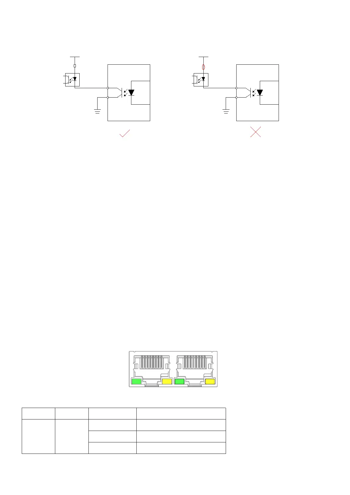
未接入继电器
续流二极管极性错误
DC12-24V
光耦
伺服驱动器
外部地
OUT1
DG
未接入限流电阻
1.4 Connection EtherCAT
Please use CAT5E (or higher level) network cable.
The Ethernet input interface IN is connected to the Ethernet output interface OUT of the
previous driver on the controller or the bus. The Ethernet output interface OUT is connected to
the Ethernet input interface IN of the next driver on the bus. If the driver is the last node on the
bus, you only need to connect the Ethernet input interface IN.
1.4.1 EtherCAT status indicator
The yellow light of RJ45 is used for Link status, indicating whether there is a network cable
connection.
The green light of RJ45 is used for Activity state, indicating whether there is data
communication.
RUN/ERRLED indicator: