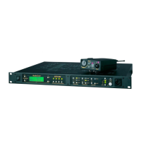
8 Getting Started, Zeus™ DSP Intercom Matrix
J25
J26
J27
90-250 VAC
50/60 HZ
TO PC
UIO/PAP/LCP
GPI
R
TELEX COMMUNICATIONS,INC.
Minneapolis, MN U.S.A.
Telex
J13 J16
J9 J12
J5 J8
J1 J4
J21 J24
J17 J20
ID
2
ID
1
ID
3
ID
4
ID
6
ID
5
ID
7
ID
8
ID
2
ID
1
ID
3
ID
4
ID
6
ID
5
ID
7
ID
8
ID
2
ID
1
ID
3
ID
4
ID
6
ID
5
ID
7
ID
8
CAUTION
1A 240V SB
TO REDUCE RISK
OF FIRE REPLACE
WITH SAME TYPE
FUSE
POWER
STATUS
RESET
TM
1 8 16 24
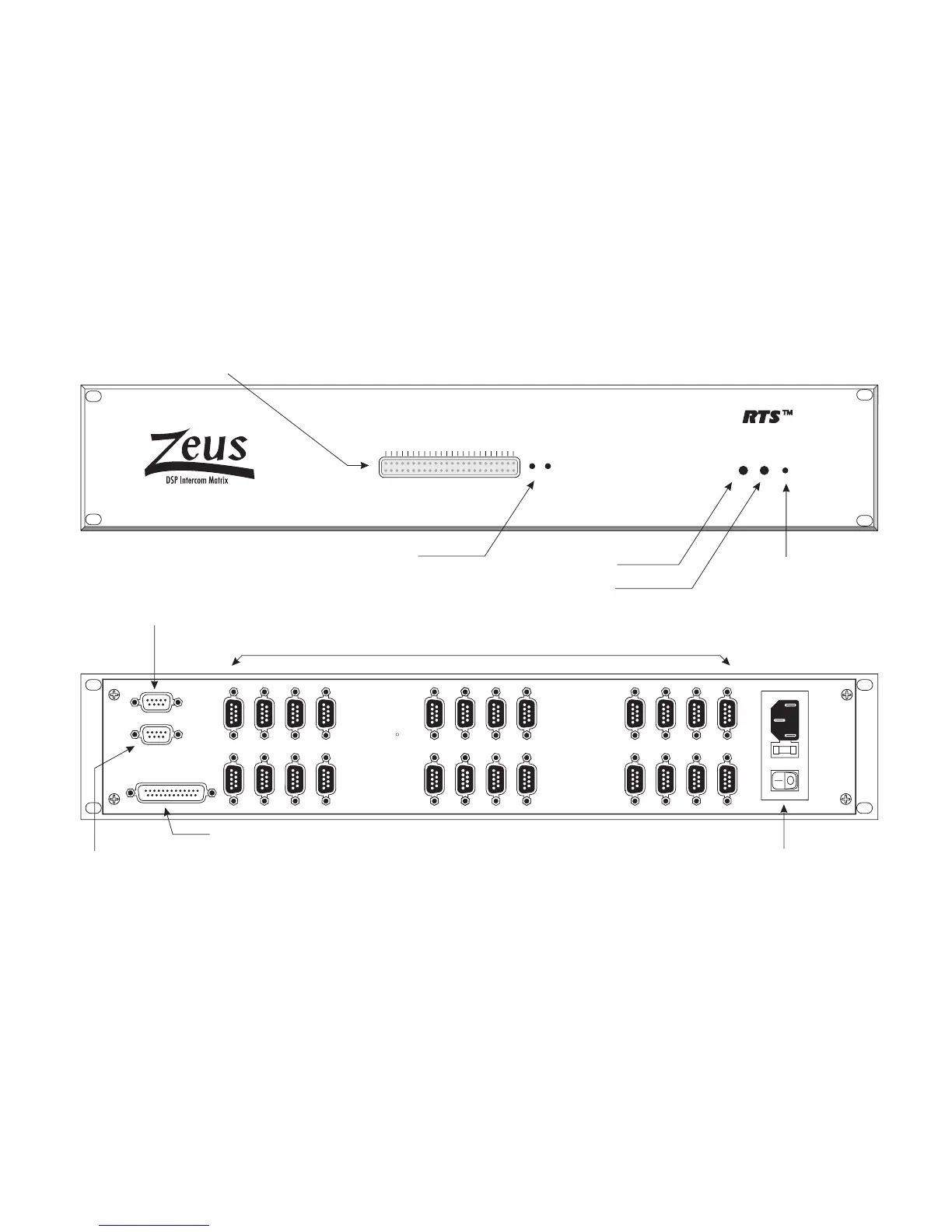
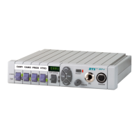
Status Indicators: 2 rows of 24 LED's each
Top Row: Green "keypanel connected" indicators. One for each intercom port. On only when a keypanel or TIF-951 is connected and operating on the port.
Bottom Row: Red "frame activiity" indicators. LED 1 On = System Ok. LED 2 On = Audio Ok. LED 3 On = ZEUSedit on-line. LED 4 = UIO-256 connected
LED 5 = LCP-102 connected. LED's 6-24 for service only
Green Power Indicator
2-color Status Indicator: Green = Normal, Red = Fault
Intercom Port Connectors: J1-J24 indicate ports 1-24.
ID1-ID8 indicate the ID numbers to use when setting keypanel addresses.
Connectors are 9-pin male D-sub.
Configuration Computer Connector:
9-pin female D-sub. Connects to a
computer running ZEUSedit. Uses a
standard RS232 serial cable.
Multi-purpose accessory connector: 9-pin female D-sub. Connects to UIO-256, LCP-102, and Program Assign Panels (PAP).
Recessed Reset Pushbutton
Recessed Diagnostic Pushbuttons
(Service only)
General Purpose Interface Connector: 25-pin female D-sub
Universal AC Power Connector with
Fuse and Power Switch: Automatically
accepts 90-250 VAC, 50/60 Hz.
Figure 1. Reference view for Zeus DSP Intercom Matrix