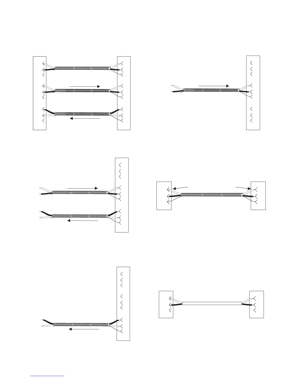
6.4 Cable Diagrams
Getting Started, Zeus™ DSP Intercom Matrix 23
DE-9P (MALE)
TO KEYPANEL OR TIF-951
DE-9S (FEMALE)
TO ZEUS J1-J24
1
2
6
4
5
9
7
8
3
1
2
6
4
5
9
7
8
3
DATA
+
-
+
-
+
-
AUDIO TO ZEUS
AUDIO FROM ZEUS
Note: Shields optional. If
used, do not connect at
keypanel end!
+
-
+
-
+
-
Figure 11. Keypanel and TIF-951 Intercom cable
wiring diagram.
TO EXTERNAL
4-WIRE
AUDIO DEVICE
DE-9S (FEMALE)
TO ZEUS J1-J24
1
2
6
4
5
9
7
8
3
AUDIO TO ZEUS
AUDIO FROM ZEUS
Note: Shields optional. If
used, do not connect at
external device end!
+
-
+
-
+
-
+
-
Figure 12. A cable to connect a 4-wire intercom
station other than a keypanel.
TO AN EXTERNAL
AUDIO INPUT
1
2
6
4
5
9
7
8
3
+
-
DE-9S (FEMALE)
TO ZEUS J1-J24
AUDIO FROM ZEUS
Note: Shields optional. If
used, do not connect at
external device end!
+
-
Figure 13. An audio output cable from Zeus to an
external device.
FROM AN EXTERNAL
AUDIO SOURCE
1
2
6
4
5
9
7
8
3
+
-
DE-9S (FEMALE)
TO ZEUS J1-J24
AUDIO TO ZEUS
Note: Shields optional. If
used, do not connect at
external device end!
+
-
Figure 14. An audio input cable to connect an ex-
ternal audio source.
TO COMPUTER
COM PORT
2
2
3
3
5
5
TO ZEUS J25
DE-9P (MALE) DE-9S (FEMALE)
Note pin number switch
Figure 15. Configuration computer cable.
☞
IMPORTANT! Note that pins 2 and 3 are switched
between the two connectors!
TO LCP-102
DATA
6
2
RS485 DATA
1
7
2
1
TO ZEUS J26
DE-9P (MALE) DE-9S (FEMALE)
-
+
-
+
Figure 16. LCP-102 interconnect cable.