J Line Pump
Horizontal Double Suction Centrifugal Pump – API 610 Process Pump
36 V1.032818
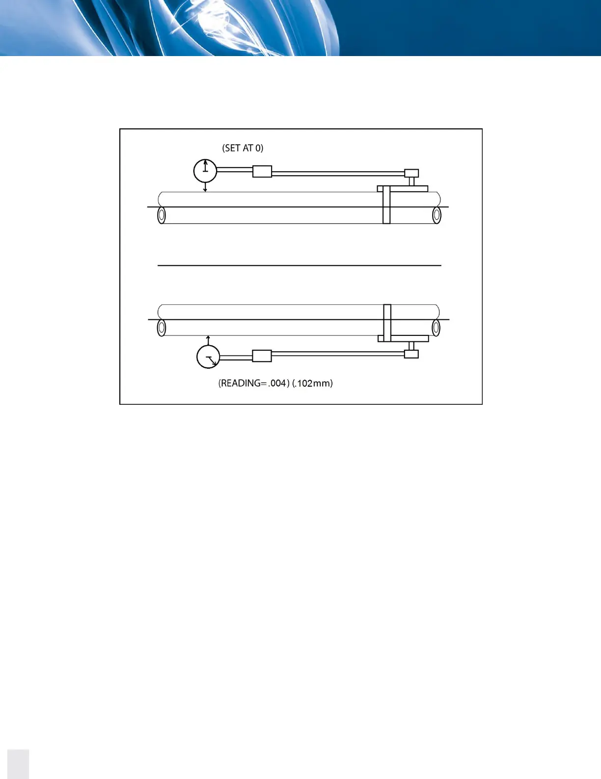
The next step is to determine indicator sag. Set up your bracket arrangement on a pipe. Set the indicator
at '0' on top. Roll set up until indicator is at the bottom of pipe. It will read negative. In this example, it
was found to be -0.004 inch (-0.102 mm).
Figure 5.9. Indicator sag in across the disc pack alignment analysis example.
With the indicator bracket attached to the pump hub, reading out the center member a convenient
distance, (in this example 8 inches [203.2 mm] was used) rotate the unit in 90° increments and take
readings.
Bottom reading is then corrected for indicator sag. The indicator sag in the example was determined to
be -0.004 inch (-0.102 mm). The -0.004 inch (-0.102 mm) was subtracted from -0.025 inch (-0.635 mm)
indicator reading to give an actual of -0.020 inch (-0.508 mm) reading.
As this is a TIR (Total Indicator Reading) it is two times the actual center member center line location
relative to the pump shaft extension or -0.020 inch (-0.508 mm) / 2 inches (50.8 mm) = -0.010 inch
(0.254 mm). (What we are trying to do here is to determine the angle the center member makes with
respect to the pump shaft.)
A plus reading at the bottom indicates that the center member tips down as it extends away from the
pump. Using a scale of one small division on the graph equals 0.001 inch (0.0254 mm); plot the
0.010 inch (0.254 mm) as shown in the example.