J Line Pump
Horizontal Double Suction Centrifugal Pump – API 610 Process Pump
37 V1.032818
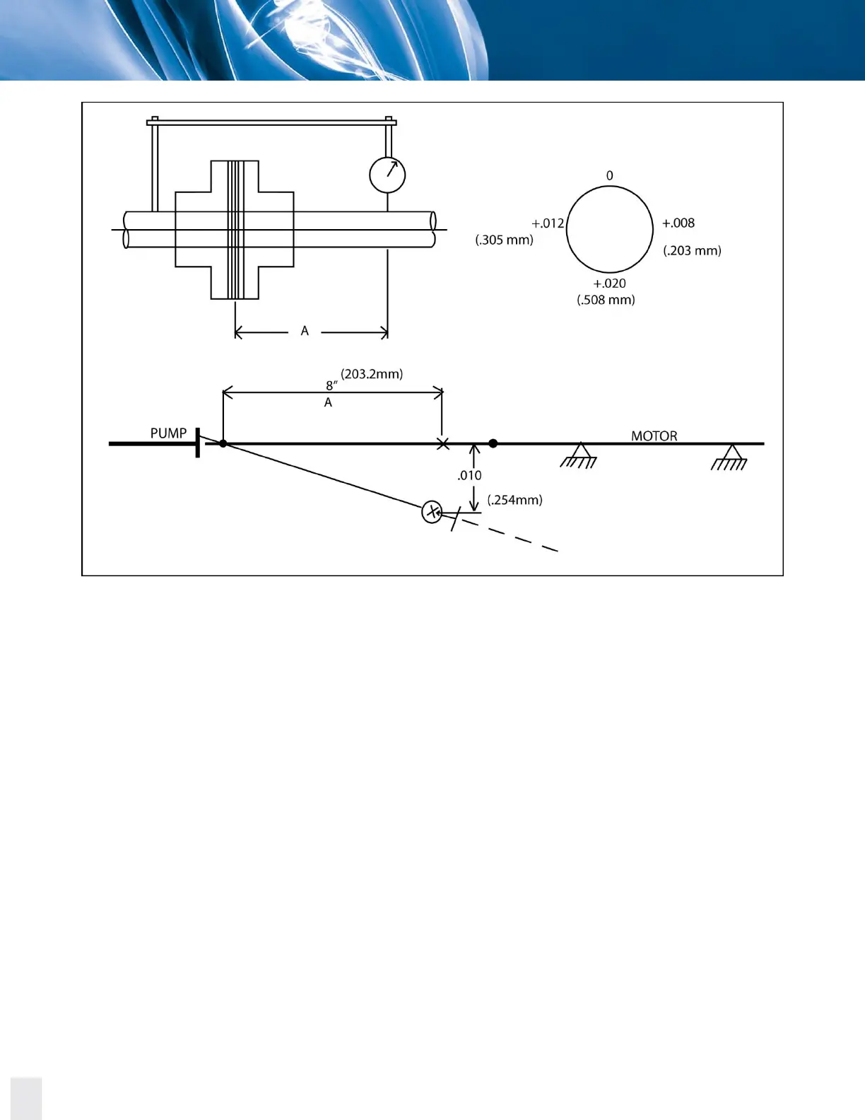
Figure 5.10. Plot of the plus reading in the across the disc pack alignment analysis example.
Now with the indicator bracket attached to the motor hub reading out on the center member, rotate
the unit in 90° increments and take readings.
Bottom reading is corrected for indicator sag: ±0.008 inch (±0.203 mm) -0.004 inch (0.102 mm) =
+0.012 inch (+0.309 mm). This is TIR so actual is +0.006 inch (+0.152 mm). (What we are trying to do
here is determine the angle the center member makes with respect to the motor shaft.)
The minus reading on the bottom indicates that the center member tips up as it extends away from the
motor. Using a scale of one small division on the graph equals 0.001 inch (0.025 mm), plot the 0.006 inch
(0.192 mm) as shown on the example.
The motor shaft can now be drawn in because two points along it have been defined: 1. Center of the
flex element. 2. The point just plotted 0.006 inch (0.152 mm) below center member. The shimming
requirements can now be read off the plot where the motor shaft intersects the planes of the motor
feet.