26 / 72
Horizontal End Suction Pump for Chemical Process, ASME B73.1-2001
Installation, Operation, and Maintenance Manual – CPP21
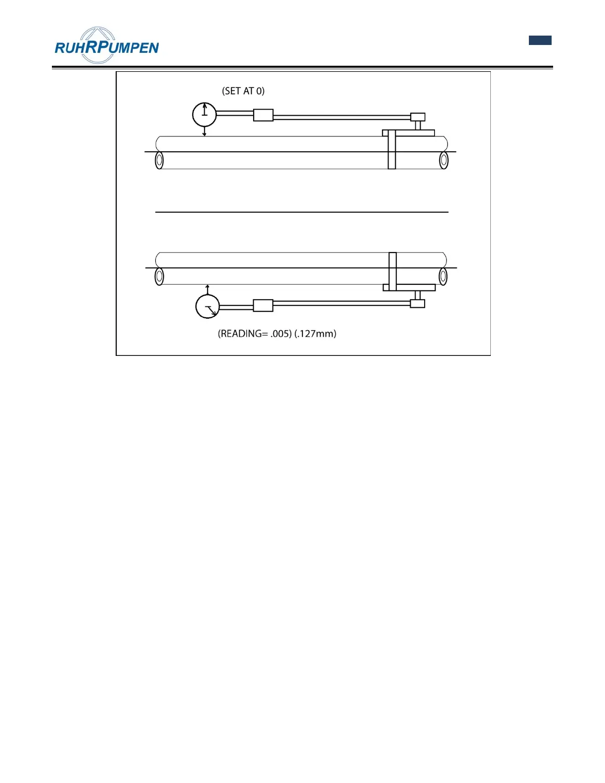
Figure 5.2 Indicator sag.
With the indicator bracket attached to the motor hub reading off the pump hub, rotate unit in 90° increments
and take readings.
Bottom reading is then corrected for indicator sag. Indicator sag in the example was determined to be
0.005 inch (0.127 mm). The -0.005 inch (-0.127 mm) was subtracted from the -0.025 inch (-0.639 mm) indicator
reading to give an actual -0.020 inch (-0.508 mm) reading.
As this is a TIR (Total Indicator Readout) it is two times the actual shaft to shaft rotation 0.020 inch (0.508 mm)/
2 inch (50.8 mm) or 0.010 inch (0.254 mm) is used to show where the motor shaft extension is relative to the
pump shaft center line at the hub. Minus at the bottom indicated motor shaft extension is low compared to the
pump. Using a scale of one small division on the graph equals 0.001 inch (0.0254 mm); plot this point as show in
the example.