28 / 72
Horizontal End Suction Pump for Chemical Process, ASME B73.1-2001
Installation, Operation, and Maintenance Manual – CPP21
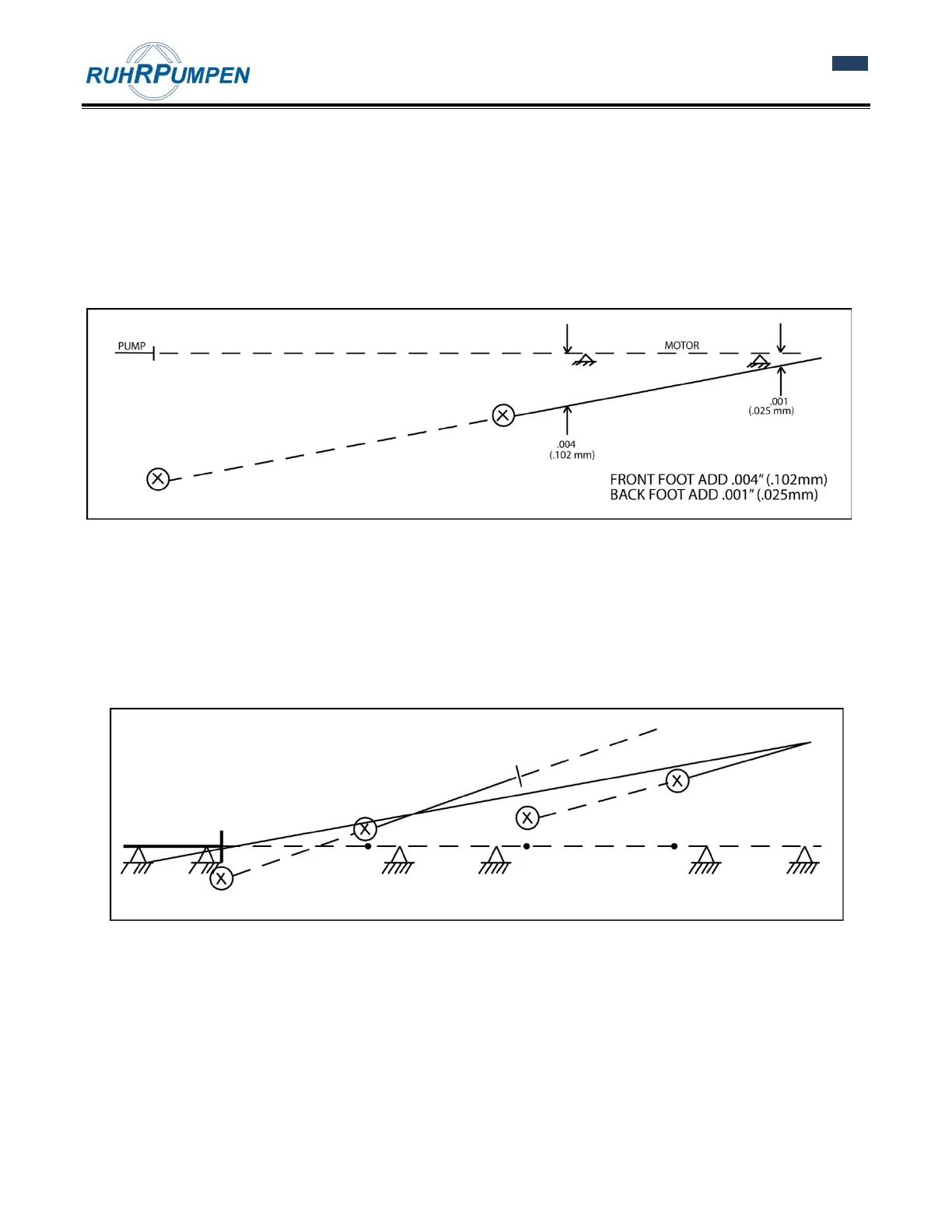
Drawing a straight line through these two points crossing the plane of the two motor feet. The shim adjustment
can now be read directly off the graph. In this example, 0.004 inch (0.102 mm) should be added to the front foot
and 0.001 inch (0.025 mm) should be added to the back foot.
This solution can also be done by the use of pre-programmed, hand calculators for faster results.
For the horizontal (side to side) results, the same procedure is used. Algebraically subtract the side to side
readings. Indicator sag can be ignored as it cancels out. Plot these readings and the results can be read off the
graph plot.
Figure 5.5 Final graph plot for reverse indicator alignment graphical analysis.
C. REVERSE INDICATOR ALIGNMENT MORE THAN TWO UNITS GRAPHICAL ANALYSIS
This method lends itself very well in solving alignment problems of three or more pieces of equipment in a line.
To solve this problem, follow the steps already outlined for each coupling in the train. Plot the shaft to shaft
relationship of each set of shafts. Look at the total picture. In this example, a line was drawn through the
average of all points plotted. The units were then aligned to this mean line.
Figure 5.6 Reverse indicator alignment of more than two units.
D. ACROSS THE DISC PACK ALIGNMENT GRAPHICAL ANALYSIS
When the distance between disc packs is long where it is not practical to try to span the distance with indicator
bracketry, the 'across the disc pack method' can be used.
On a sheet of graph paper, lay out the equipment that you are trying to align. You should use a scale that is
convenient to the size of the graph paper. The distances that are critical are: